background image

Step 6: Once more, with feeling 

Now that you’ve got one of the XBees set up as a router/end device, you can unplug it from the 
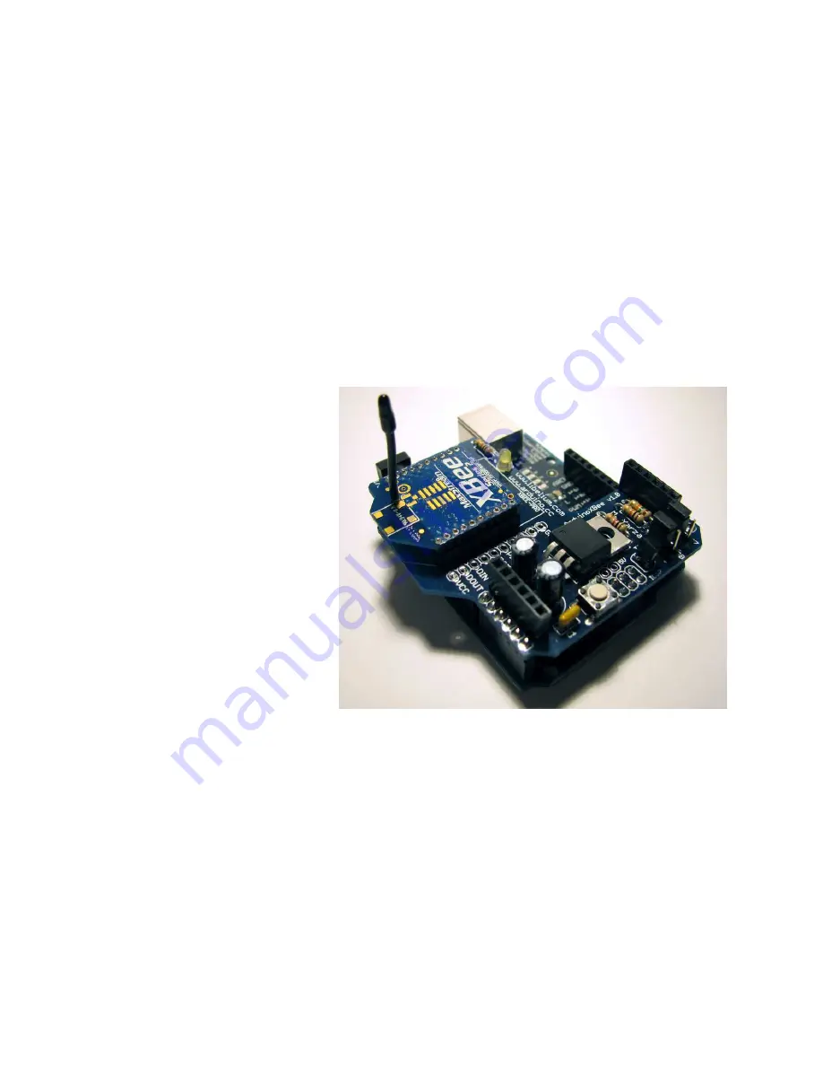
XBee Breakout board and install it in whetever device it will communicate with; I recommend 
plugging it into an XBee Shield for the Arduino at this point. You may also want to put a sticker 
or label on this XBee to identify it as your router. Set it aside for the moment. 
 
Now plug your other XBee module into the XBee breakout board and repeat steps 2 through 5 
with this module. However, in step 4 you will select the “ZNet 2.5 Coordinator AT” as the 
firmware and set the Node Identifier as “coordinator” or something similar. Once you’ve updated 
to the coordinator firmware, the “Associate” LED should begin blinking once-per-second while 
the “On” LED should remain lit. Confirm the settings in the terminal and move on to the next 
step. 
 

Step 7: Creating the network 

At this point, you should have one 
XBee updated with the “ZNet 2.5 
Router” firmware plugged into the 
XBee Shield on top of an Arduino 
and the other XBee updated to the 
“ZNet 2.5 Coordinator” firmware 
and connected to the FT232 
breakout which is plugged into 
your computer. The “Associate” 
LED on the Coordinator XBee 
should be blinking once-per-
second. 
 
On the XBee shield, you should 
see a pair of jumpers labeled 
“XBEE/USB”. Remove both of 
those jumpers for now.
 Connect 
your Arduino to a power source 
(USB or External, doesn’t matter for now). After powering up, the “Associate” LED on the 
XBee shield should begin blinking twice-per-second – congratulations; the XBees have formed a 
network! 
 
Using the X-CTU terminal connected to the coordinator, type “+++”, wait for the “OK” 
response, then type “ATND”. The XBee will respond with the serial number, node identifier and 
other information about the router XBee connected to the Arduino. 
 

Содержание ZNet 2 Series

Страница 1: ...ncluded with NKC kit 1 Male Header row for XBee breakout Sparkfun SKU PRT 00117 or included with NKC kit 1 FT232RL Breakout Board Sparkfun SKU BOB 00718 male or female headers for the FT232RL Breakout...

Страница 2: ...circuit on your bread board using the diagram Instead of using a reset switch I just plug one end of a jumper wire into the XBee reset pin and leave the other end of that jumper hanging off the edge...

Страница 3: ...nected to the XBee should light up and stay on assuming your XBee shipped as a Router End Device and there is no Coordinator around to connect to Download the X CTU software from Digi and install it T...

Страница 4: ...ent settings of the attached XBee Select ZNet 2 5 Router End Device AT as the firmware in the pull down menu Change the Node Identifier to something like router1 You may want to change the PAN ID to a...

Страница 5: ...for Coordinator Type ATID to check the PAN Network ID that the XBee is using It should respond with 123 or whatever unique PAN ID you set in step 4 Type ATNI to check the Node Identifier The XBee sho...

Страница 6: ...m the settings in the terminal and move on to the next step Step 7 Creating the network At this point you should have one XBee updated with the ZNet 2 5 Router firmware plugged into the XBee Shield on...

Страница 7: ...the serial connection once per second while blinking the LED on pin 13 Used for testing serial devices such as the XBee Adapted from the SoftSerial Demonstration code define ledPin 13 byte pinState 0...

Страница 8: ...wo XBee modules and you want two routers end devices to talk to one another you ll need to set the Destination Nodes for each module You can easily do this by entering command mode typing and then sen...

Отзывы: