


6
parameter controls the degree of symmetric
detuning of the additional voices around the
central voice.
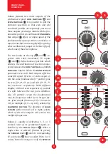
The lin fm input
30
together with the as-
sociated slider
31
offers a deep through-ze-
ro frequency modulation of the signal. The
modulator input is AC coupled (cut below
20Hz) and accepts full-bandwidth signals up
to 10Vpp. Bear in mind that while the funda-
mental frequency is modulated to the degree
you set, the overtones are modulated much
wider because the depth scales with their
relative frequency. With a wideband carrier,
the spectrum of an FM’d signal explodes into
MHz range and most of it will be removed by
the anti-aliasing protection. Classic clangor-
ous FM sounds are obtained with just a few
harmonic partials.
note:
Place the slider at
minimum when no modulation is applied in
order to prevent amplification of random
values read by the A/D converter which
could impact pitch stability.
SPECTRUM ANALYZER
The arc of 12 multicolor LEDs
32
shows the
power density spectrum which is the
name of the power contribution of differ-
ent frequency components of the signal in a
number of disjoint bands. Here, the 12 bands
cover the entire audible frequency range in
exponentially spaced intervals (0.8 octave
per band): below 35Hz, 35 to 63Hz, 63Hz to
113Hz, 113Hz to 204Hz, 204Hz to 367Hz,
367Hz to 661Hz, 661Hz to 1.19kHz, 1.19kHz
to 2.14kHz, 2.14kHz to 3.85kHz, 3.85kHz to
6.94kHz, 6.94kHz to 12.5kHz, above 12.5kHz.
Certainly, with only 12 bands it offers only a
crude overview of what is going on.
note:
the color temperature is mapped from dB
scale. Although the LEDs turn off below a
certain level, this does not mean there are
no spectral components in a given band, but
rather that they are too quiet to show.
THE MEANING OF SPECTRUM
PARAMETERS
The various parameters offered by Odessa
have been selected by observing how spec-
tra of different sounds vary, and how these
differences could be generalized to a set of
global features without losing the ability to
synthesize a broad range of sounds. The de-
fault values of knobs shown in fig. 1 produce
the most common waveform in synthesizers:
the sawtooth wave. It became so popular be-
cause it is quite easy to generate in analog
circuits, and also because it’s a good starting
point for many synthetic timbres.
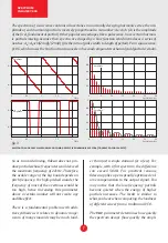
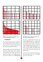
The partials parameter controls the num-
ber of harmonic components in a signal,
from 1 to 512. Turning it down limits the
spectrum to the initial N partials, until the
signal resembles a single sinusoid (fig. 4).
note:
you can’t turn off the fundamental.
However, since it is separately available on
a dedicated output, you can subtract it from
your signal using a simple patch.
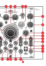
WORKING CLASS ELECTRONICS
MADE IN THE EUROPEAN UNION
XAOCDEVICES.COM
POWER
CONNECTOR
STRIPE
FUNDAMENTAL OUT
SINE
SQU
ARE
V·OCT
LIN FM
NULL
TR 1
TR 2
REV. 06.2019
1975 V
ARIABLE SPECTR
UM
HARMONIC CL
US
TER OSCILL
ATOR
CAUTION!
BEFORE CONNECTING
THE EXPANDER MODULES PLEASE
REFER TO THE MANUAL! IMPROPER
CABLE ORIENTATION WILL
CAUSE SERIOUS DAMAGE!
CAUTION!
DO NOT ATTACH THE
POWER CONNECTOR TO ANY OF THE
EXPANDER HEADERS!
LEIBNIZ
SUBSYSTEM
TERMINAL
STRIPE
HEL
EXPANDER
fig. 2
fundamental output
configuration jumper


