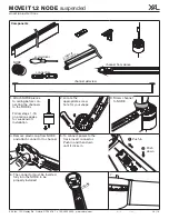
1. Layout track(s) and mark
mounting points
3. Insert feeder through hole in track
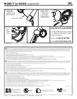
5. Insert rope fixation into top of
track and turn clockwise to secure
9. Thread feeder through cover
plate
8. Thread aircraft cable through
cover
11. Use screws to secure strain relief
4. Assemble barrel mount and rope
fixation
6. Adjust aircraft cables to poper
height
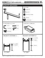
Turn OFF power source before
installation
7. Thread aircraft cable through
bracket
7 ⅛
"
2 ⅝"
15"
2. Install converter box (ceiling
/
utility room). See page 4 chart for
max. distance
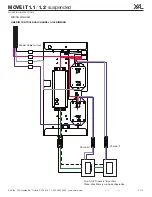
RED
+
BLACK
—
10. Thread feeder through bracket
12. Place bracket into junction-box
13. Screw bracket into J-box
14. Click cover onto mounting
plate springs
23.
25.
22.
Insert T-Connector
(optional)
:
Use screws to attach T-connection
24.
Insert X-Connector
(optional)
:
Use screws to attach X-connection
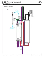
Please see wiring
diagram on page 2
2"
18. Use screws to secure connector
19. Slide next track onto linear
connector
15. Connect feeder to converter box
17. Insert linear connector
16. Snap feeder clip into track
21 B.
Track 1.2
: Turn tentioning
screw counter-clockwise
Repeat steps 17-21 for additional
channels
20. Use screws to secure connector
again
21 A.
Track 1.1
: Turn tentioning
screw clockwise
RED
+
BLACK
—
1"
MOVE IT 1 .1
/
1.2
suspended
MOUNTING INSTRUCTIONS
XAL Inc. 150 Hawley Rd. Oxford, CT 06478 T: +1 203.262.9990 www.xalusa.com
MI-V02
4/13/21
12 / 14

