background image

9

8

 C

ONNECTING

 U

P


H

OOKING


UP


THE

 VGA S

ENDER

1. Connect the jack on the audio cable (supplied) to the audio out

jack on your PC sound card.

2. Connect the red RCA plug to the socket labelled AUDIO RIGHT

and the white RCA plug to the jack labeled AUDIO LEFT on the
VGA Video Sender.

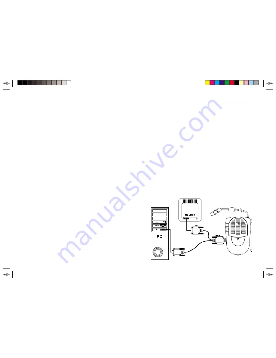
3. Connect the VGA cables as show below so that the VGA out from

your PC connects to the VGA input on the VT37A and then also
passes to the VGA input on your monitor.

4. Set the channel switch (on the TOP of the unit) to channel A (to

the RIGHT).

5. Plug the VGA Video Sender's Power Supply (the larger of the

two power supplies) into a convenient 120 volt wall outlet and
plug its jack into the VGA Video Sender.

6. Position the VGA Video Sender in a convenient location and

orient the antenna so that the flat side points in the direction of the
room where you will be installing the Video Receiver.

P

Before you start installing your VGA System it is recommended that
you read this entire owner's manual. This will familiarize you with
the basic hardware installation. Then install the hardware (do NOT
connect the USB connector yet). You will be able to see a picture
from your PC on our TV screen. You can then visit www.x10.com/
software and download the "Boom" program, which will give you
control over what is sent from your PC to your TV.

Install the Boom software (do NOT plug the VGA sender into your
USB port yet). When instructed to do so by the Boom installation
program, plug the VGA sender into your USB port. Windows will
tell you it has found new hardware and will automatically install the
X10 USB driver for the VGA sender.

B

EFORE

 Y

OU

 S

TART

USB port connecter (do not
connect until you install the
Boom software)

* If your PC does not have a USB port you won't be

able to use the remote control features of the UR83A.

Содержание VK72A

Страница 1: ...OWNER S MANUAL VGA Video Sender MODEL VK72A INCLUDES VT37A USB SENDER AND VR30A RECEIVER VT37A VR30A...

Страница 2: ...erference Relocate the equipment with respect to the radio TV Move the equipment away from the radio TV Plug the equipment into an outlet on a different electrical circuit from the radio TV experienci...

Страница 3: ...Channel Switch CONTROLS AND CONNECTIONS SENDER SIDEVIEW VGA In CONTENTS CONTROLS AND CONNECTIONS 5 SENDER 6 RECEIVER 7 BEFORE YOU START 8 CONNECTING UP 9 HOOKING UP THE SENDER 9 HOOKING UP THE RECEIV...

Страница 4: ...Power Supply Jack 2 4 GHz Channel Switch on bottom TV Channel Switch on bottom ON OFF Switch on side SENDER 310 MHz Antenna for use with UR83A remote Audio Input Jacks Power Supply Jack 2 4 GHz Video...

Страница 5: ...the direction of the room where you will be installing the Video Receiver P Before you start installing your VGA System it is recommended that you read this entire owner s manual This will familiariz...

Страница 6: ...the Video Receiver s Power Supply the smaller of the two power supplies into a 120 volt wall outlet and plug its jack into the Video Receiver 3 Position the Video Receiver in a convenient location suc...

Страница 7: ...LESHOOTING IF YOU ARE NOT GETTING ANY AUDIO OR VIDEO AT ALL FROM THE VR30A Check that the CHANNEL slide switch labeled A B C D on both units is set to the same letter Check that both the transmitter a...

Страница 8: ...IPPING DAMAGE UNITS TO BE RETURNED SHOULD BE PACKED CAREFULLY THIS WARRANTY DOES NOT EXTEND TO ANY X10 PRODUCTS WHICH HAVE BEEN SUBJECT TO MISUSE NEGLECT ACCIDENT INCORRECT WIRING OR TO USE IN VIOLATI...

Страница 9: ...X10 com a division of X10 Wireless Technology Inc Returns Depot 3824 North 5th St Suite C North Las Vegas NV 89030 VK72A 05 01...

Отзывы: