background image

S p e c t r a L i g h t   Q C  

19


  F1, F2, F3, and UV select the front or rear lamp location.  

  HZ select front 1, front 2, rear 1, or rear 2 lamp location. 


4.


Press the 

EDIT

 switch to access the editing screen.  

5.


Enter the required serial number (see below).  


Entering serial number using the front panel: 

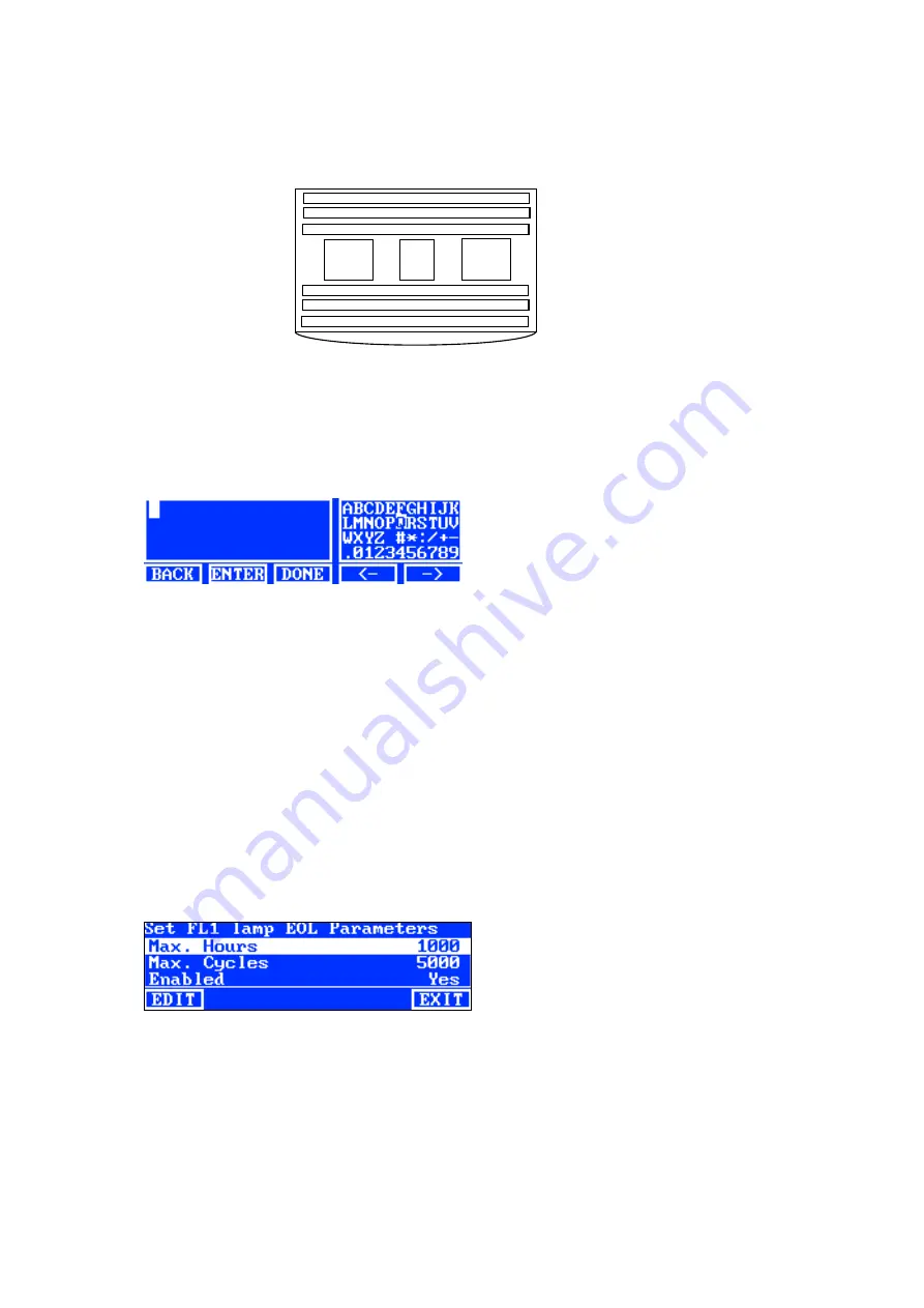
  Use the left


(

), right (►), up (

), and down (

) arrow switches to highlight the letter/number in the list. 

  Press the 

ENTER

 switch to add it to the name. 


  Continue with additional letter/numbers until the number is complete.  

  Press the 

DONE

 switch and then the 

Yes

 switch when finished. 


Entering serial number using the application: 

  Make sure the editing window is displayed and enter required serial number. 

  Press 

Enter

 key on the keyboard when finished. 

NOTE

: The DEL option is used to delete the current lamp serial number from the selected lamp location. 


Setting EOL Parameters  

This option is used to set the end of life parameters for each lamp. When the hours or cycles are reached for 

the lamp, an EOL message appears on the main menu when the lamp is turned on. If the EOL lamp option is 

disabled, no message appears. 

NOTE:

 This setting should only be used if changing the EOL from the factory configuration. 

1.


To set EOL, use the up (

) and down (

)


arrow switches to highlight the lamp location. 

2.


Press the 

EOL

 switch to access the EOL screen. 


3.


Use the up (

) and down (

)


arrow switches to highlight the desired parameter. 

4.


Press the 

EDIT

 switch to access the editing screen. 

5.


Use the up (

) and down (

)


arrow switches to enter desired hours, cycles or enabled/disabled option. 

NOTE

: Holding down the switch quickly increments through the values. 

6.


Press the 

OK

 switch to save. 

7.


Press the 

EXIT

 switch to exit the screen. 

Left 

Right 

Rear 

Front 

Luminaire lamp 

position diagram 

2


Top View 

Содержание Macbeth Lighting SpectraLight QC

Страница 1: ...Operation Manual Register your product and get access to important product updates exclusive content service support and other tools to help you get the most of your product www xrite com registration ...

Страница 2: ......

Страница 3: ... MANNER NOT SPECIFIED BY X RITE THE PROTECTION PROVIDED BY THE EQUIPMENT MAY BE IMPAIRED CAUTION DO NOT connect to an ungrounded outlet DO NOT use with 2 wire extension cords or adaptors WARNING This instrument is not for use in explosive environments Instructions for disposal Please dispose of Waste Electrical and Electronic Equipment WEEE at designated collection points for the recycling of such...

Страница 4: ...tic mechanical optical manual or otherwise without the prior written permission of an authorized officer of X Rite Incorporated Patents www xrite com ip 2019 X Rite Incorporated All rights reserved X Rite and SpectraLight are registered trademarks of X Rite Incorporated All other logos brand names and product names mentioned are the properties of their respective holders Warranty Information X Rit...

Страница 5: ...the X Rite Support or the nearest X Rite Service Center if you believe that the unit does not work anymore or does not work correctly THESE WARRANTIES ARE GIVEN SOLELY TO BUYER AND ARE IN LIEU OF ALL OTHER WARRANTIES EXPRESSED OR IMPLIED INCLUDING BUT NOT LIMITED TO THE IMPLIED WARRANTIES OF MERCHANTABILITY FITNESS FOR A PARTICULAR PURPOSE OR APPLICATION AND NON INFRINGEMENT NO EMPLOYEE OR AGENT O...

Страница 6: ...ing the Light Sources SEL 22 Edit Operator Profiles OPER 23 Date and Time Setup TIME 24 User Settings USER 25 Display System Information INFO 26 Daisy Chain Configuration Setup CHAIN 27 Operation 29 Selecting a Lamp Source 29 Auto Sequence 30 Display Adjustment 31 Sensor Display for service only 32 System Operating Language 32 Running System Reports 32 Remote Control Operation 35 Operation 35 Remo...

Страница 7: ...in light sensors to monitor light levels Adjustable light levels and automatic lux control Handles for easy setup and hanging luminaires Easy handle diffuser with safety switch Easy to replace daylight lux attenuators snap in mechanism optional accessory Built in real time clock Computer interface for control and monitoring Versatile user interface configurations in English or Chinese Unpacking Yo...

Страница 8: ...iewing booth should be constructed To avoid color misjudgments the background on which the sample is placed and the surrounding area of view should be neutral in color and have a low gloss Do not block vents luminaire s should be installed so that it is a minimum of 200 mm 8 inches from the next luminaire or a wall surface It is recommend that luminaires are positioned no less than 60cm 2 feet fro...

Страница 9: ... into bottom panel 3 While supporting the rear panel 2 position the left panel 3 with the smooth side out over the top edge of the rear panel 2 4 Slide the left panel 3 downward along the interlocking channel until the left panel 3 front tab inserts into the bottom panel 1 Fasten the left panel 3 to the bottom panel and rear panel by securing it with four screws as shown in Figure 3 Figure 3 Left ...

Страница 10: ... panel 4 to the bottom panel and rear panel by securing it with four screws as shown in Figure 4 Figure 4 Right panel into rear and bottom Panel 7 Slide the pivot slots on the front panel 5 onto the pivots located on each of the two side panels 8 Rotate the front panel upwards toward the unit until the magnets come into contact with the front panel See Figure 5 Figure 5 Front panel assembly 4 1 2 ...

Страница 11: ...orm the following steps 3 Carefully unpack and remove the overhead luminaire from its shipping container using the handles brackets located on the short sides NOTE Be sure to remove all packing foam from inside the luminaire 4 With its controls and indicators facing to the front carefully place the luminaire on top of the viewing booth Align the luminaire on the viewing booth 5 Secure the luminair...

Страница 12: ...ed position and secure it in place with the latch CAUTION Ensure that the diffuser latch is secured before releasing Failure to do so may result in the diffuser sliding out of position 11 Reinstall the front panel CAUTION Before plugging in the unit verify the voltage indicated on the SpectraLight QC back label complies with the AC line voltage in your area If not contact X Rite or an authorized r...

Страница 13: ...r using the handles brackets located on the short sides CAUTION Ensure adequate support in the next step Each unit weighs 40 5 kg 89 3 lbs Chains must be rated for 81 6 kg 180 lbs each 3 Attach karabiners and chains not included to each of the brackets and suspend the unit s at the appropriate height and angle over the work area Luminaires should be installed so that it is a minimum of 200 mm 8 in...

Страница 14: ...he luminaires at the front near the diffuser latch Use the cable clips to hold the cables in place Refer to Figure 11 Master Slave Slave Figure 11 Luminaire Daisy Chain Connection CAUTION Before plugging in the unit verify the voltage indicated on the SpectraLight QC back label complies with the AC line voltage in your area If not contact X Rite or an authorized representative 10 Plug the SpectraL...

Страница 15: ...per shutdown before powering on again If you attempt a power on less than 5 seconds after shutdown the unit may not power on If this occurs shutdown the unit wait at least 5 seconds and then power it on using the power switch Navigating the Screen The five switches at the bottom of the display panel are used to select lamp sources advance to additional screens and perform editing functions The opt...

Страница 16: ... GB Windows Vista SP2 32 or 64 bit RAM 1 GB Windows 7 32 or 64 bit RAM 1 GB Monitor screen resolution of 1024 x 768 1 GB hard disk free Software Installation IMPORTANT You must be logged on as an administrator or a member of the Administrators group in order to install the application on a computer with Windows XP Vista Business or 7 Professional Operating System 1 Insert the software CD into the ...

Страница 17: ...til Setup appears in the display screen 2 Press the ADMIN switch to access the Advance Setup 1 screen NOTE If password protection was previously setup you will need to enter the password before accessing the ADMIN options Owner Profile Setup OWNER 1 Press the OWNER switch to access the Owner screen The following are descriptions of the Owner Options Owner Options Text Entry Factory Default Descrip...

Страница 18: ...ter key on the keyboard when finished 5 When finished with owner options press the EXIT switch to exit the Owner screen Primary System Settings SYS 1 Press the SYS switch to access the System Settings screen The following are descriptions of the system settings System Settings Value or option selection Factory Default Description DL UV Auto Manual Auto Automatic add UV to daylight or manually add ...

Страница 19: ...uto Off Timer min 0 to 999 minutes 5 Set the amount of time in minutes that the DL HZ and HL lamps change to the FL1 lamp Set to 0 if you do not want the lamp change Standby Timer min 0 to 999 minutes 30 Set the amount of time in minutes that the unit goes into standby after the last button was pressed Any button pressed on the display panel will reactivate the unit Message Codes 0 to 255 100 Mess...

Страница 20: ...witch to exit the screen Selecting Type of Lamp Select the lamp type installed from the list If the lamp type is not in the list please consult your technical support NOTE This setting should only be used if changing the lamp type from the factory configuration 1 To set type use the up and down arrow switches to highlight the lamp location 2 Press the TYPE switch to access the Select Type screen 3...

Страница 21: ...mp serial number from the selected lamp location Setting EOL Parameters This option is used to set the end of life parameters for each lamp When the hours or cycles are reached for the lamp an EOL message appears on the main menu when the lamp is turned on If the EOL lamp option is disabled no message appears NOTE This setting should only be used if changing the EOL from the factory configuration ...

Страница 22: ...d see below 4 Edit the remaining profile parameters See Editing a Profile that follows Copying an Existing Profile 1 If you want to copy an existing profile highlight the profile and press the COPY switch The profile will be used as the template for the new profile 2 Use the up and down arrow switches to select the location to copy the profile This can be a free location or you can overwrite and e...

Страница 23: ...creen 3 Enter the required parameters see below 4 When finished press the EXIT switch to exit the Edit Profile screen Single Lamp Tri Lux Operation fluorescent tubes only The Edit screen is used to edit the high normal and low lamp lux values The Norm lux value is used for standard operation The Tri Lux option must be selected for the Up Down keys option in System Setting to allow the three lux se...

Страница 24: ...e the switch name i e DL to the desired menu location 4 Press SEL switch again to set the location 5 Continue with additional switch locations Setup Auto Sequence PROG The SpectraLight QC can be programmed to run a sequence of light sources for the selected profile each for a specified period of time 1 999 seconds 1 Press the PROG switch to access the auto sequence screen for the selected profile ...

Страница 25: ...ed operator 2 Press the EDIT switch at access the Edit Operator screen The following are descriptions of the Operator Options Operator Options Text Entry Value or Option Factory Default Description Name Text Blank Enter operator name with a maximum of 15 characters ID Text Blank Enter operator ID with a maximum of 15 characters The ID appears on the reports Gender Male Female Blank Select operator...

Страница 26: ...the character to the name Continue with additional letter numbers until the name is complete Press the DONE switch and then the Yes switch when finished Entering text using the software application Make sure the editing window is displayed and enter required name 15 characters maximum Press Enter key on the keyboard when finished Date and Time Setup TIME The time screen is used to set the current ...

Страница 27: ...r settings User Settings Value or option selection Factory Default Description Operator 1 to 16 Select the operator from the list Operator name will appear on the main menu Profile 1 to 16 Select the profile from the list Profile name will appear on the main menu Attenuator 75 50 25 0 25 D65 50 D50 NOTE Make sure the setting matches the attenuator cover installed otherwise the system will not work...

Страница 28: ...device serial number etc A system log file can also be viewed from this screen 1 From the main menu of the SpectraLight QC press and hold the MORE switch until Setup appears in the display screen 2 Press the INFO switch to access the System Info screen 3 Use the up and down arrow switches to view all system information 4 The system information is displayed Press the LOG switch to view the last 102...

Страница 29: ...on Daisy Chain Enabled Disabled Enabled Enable or disable daisy chain operation Bus Mode Serial Parallel Serial Set bus operation mode to serial or parallel Address Mode Broadcast Group Device Broadcast Set addressing mode option for the luminaires Broadcast covers all connected unit Group covers the selected group and Device is for an individual unit Group G1 to G8 G1 Set the active group for add...

Страница 30: ... EDIT switch and use the up and down arrow switches to select a group 4 Press OK to confirm the assignment 5 When finished press the EXIT switch to exit the daisy chain settings screen NOTE The BREAK switch is used to send a break signal to the daisy chain This function is used for servicing NOTE Always switch the power ON first to the Slave units and the Master unit last Units configured as Slave...

Страница 31: ...e auto off timer NOTE Lamps will not operate until the date and time for the system are set Refer to the Administrator section earlier in the Manual for instructions Main Menu 1 Main Menu 2 Momentary Held The Dim control allows you to increase or decrease the Lux or brightness of only the fluorescent and UV lamp sources The Tri Lux option allows to page through three predefined lux values set for ...

Страница 32: ... be replaced with the lamp type name CWF TL84 etc if desired Refer to the Switch Naming option procedure earlier in User Settings Auto Sequence The SpectraLight QC can be programmed to run a sequence of light sources each for a specified period of time 1 999 seconds The program is helpful if you want to view a sample under several light sources in succession and focus on the sample s appearance ra...

Страница 33: ...quence menu PAUSE Pauses the sequence and leave the current light source on Pressing the switch again resumes the sequence This is useful if you want to the light source to remain on longer than it s programmed NEXT Advances to the next source in the sequence REP Repeats the sequence after it is completed STOP Stops the sequence and exits the program Display Adjustment The brightness and contrast ...

Страница 34: ...enter the Configuration mode 1 Make sure the main power switch is off 2 Press and hold the up arrow switch and turn on the main power switch under the front edge of the luminaire Hold the arrow switch until the language menu appears 3 Use the up and down arrow switches to highlight the desired language and then press the OK switch Running System Reports The SpectraLight QC application can produce ...

Страница 35: ... L i g h t Q C 33 Conformance Report Select the required operator and profile before running the conformance report 3 Click the Conformance Report button to create and view a conformation report Sample System Report ...

Страница 36: ...S p e c t r a L i g h t Q C 34 Sample Conformance Report ...

Страница 37: ...in to turn the source off Remote Address Code Table The address code that is set in the system setting configuration must be paired with the proper dipswitch settings on the remote for the remote to operate The dipswitches are located on the back of the remote control under a cover The default address code for the system setting configuration is 1 This setting requires dipswitch A0 on the remote t...

Страница 38: ...the control box 3 Connect the other end of the cable to the left port under the front panel of the first luminaire 4 Continue connecting daisy chain cables to the remaining luminaires left port in and right port out 5 Attach the AC adapter to the control box and plug into an AC wall receptacle 6 Connect the PC to the USB port on the control box to access and configure all of the individual luminai...

Страница 39: ...ler or service center Problems and questions can also be faxed to your local X Rite office listed on our web site Luminaire Repackaging Follow the steps below to ensure that the luminaire is properly repackaged before returning for repair 1 Locate all of the original packaging materials 2 Position the left right front and back L shaped supports along the bottom edges inside the box 3 Position the ...

Страница 40: ...ION Make sure there are no objects in the way of the diffuser before opening 3 Hold the diffuser and release the diffuser latch located at the front of the unit 4 Slowly lower the front of the diffuser to its completely opened position vertical 5 Wash the interior of the diffuser glass with water containing a mild detergent rinse thoroughly and air dry Figure 12 Luminaire with Diffuser Open Main P...

Страница 41: ...may damage the filter when heated by the lamps 5 Rotate the daylight filter pack back into position and push in on the fastener button to secure Repeat procedure for other daylight filter pack 6 Reinstall the attenuators on the filter packs with the thumb screws Cleaning the Fluorescent and Halogen lamps 1 Remove dust from all remaining lamps with a clean dry lint free cloth 2 Remove dirt from all...

Страница 42: ...ylight filter pack Repeat the procedure for the other filter pack 2 Push one end of the old lamp into the spring loaded socket with pressure to release the other end from its socket 3 Lift the lamp clear of both sockets and discard in an appropriate receptacle 4 Using a piece of lens paper or equivalent between your fingers and the lamp push one end of the replacement lamp into the socket Refer to...

Страница 43: ...on holder and rotate 1 4 turn clockwise until secure 7 Plug in the AC power and turn on the power switch to begin normal operation Screen Messages Screen messages can appear on the display during error conditions or for informational purposes Some messages require user interaction to clear while others only appear momentarily and require no action If an error message persists please contact our te...

Страница 44: ...ent procedure Contact X Rite technical support NOTE For fluorescent lamps we guarantee a minimum of at least 1250 lux However due to the significant variation in commercial tubes the lux may be significantly higher Remote control not working Battery in remote is bad Replace the battery Wrong address code assigned to luminaire Refer to System Setting in the Configuration section to check address co...

Страница 45: ...tandby Power 2 W OPTICS Lamps DL Daylight Two 2 FDF 500W 120V A Incandescent A One 1 EHM 300W 120V HZ Horizon Four 4 FDF 500W 120V FL1 CWF Two 2 F30T8 CW FL2 TL84 Two 2 TLD 30W 840 SUPER FL3 U30 Two 2 FO25 830 XP ECO3 or U35 Two 2 F25T8 SPX35 ECO UV UltraViolet Two 2 F30T8BLB Daylight Filter Options D50 filter 5000 K qty 8 D65 filter 6500 K qty 8 Daylight Attenuator Options 25 Attenuator 50 Attenu...

Страница 46: ...DL on off A A on off UV UV on off HZ HZ on off MORE FL1 FL1 on off FL2 FL2 on off PAUSE AUTO STOP NEXT REP Pause Auto Sequence Go to Next Step Repeat Sequence Press and hold 2 seconds to disables auto shutoff FL3 FL3 on off 1 2 Short Long Short 5 3 Continued ...

Страница 47: ... Source AUTO TIME Set Lamp on Time in Seconds DEL Delete a Step 1 2 Long Long Short USER Edit User Settings Dim Control Language Prev Item EDIT GROUP Next Item Edit Chain Setting Enable Address Mode CHAIN Assign a device to a group BREAK Send Break to Chain EXIT 4 5 6 Continued ...

Страница 48: ...TEST Start lamp test ADMIN OWNER Edit owner information Edit System Settings Filter Attenuator SYS Advanced Setup Password Protected RESET EXIT Reset Lamp Hour Cycle RLAMP TYPE Select Lamp Type SN Enter serial number EOL Set EOL Parameters MORE EXIT Prev lamp Next lamp 7 8 10 Continued ...

Страница 49: ... Q C 47 OPER MORE PROFL Prev profile EDIT Next profile Edit a profile COPY EXIT Copy a profile DEL Delete a profile PASTE Paste a profile Prev operator EDIT Next operator Edit an operator EXIT TIME Set Date Time EXIT 9 11 12 ...

Страница 50: ...2 Ultralume 3000K U30 TL83 or F12 36 T8 lamps A L SPLU30 8 8 Ultralume 3000K U30 TL83 or F12 36 T8 lamps SPQ L U352 2 Ultralume 3500K U35 36 T8 lamps A L SPLU35 8 8 Ultralume 3500K U35 36 T8 lamps SPQ L TL842 2 Ultralume 4000K U40 TL84 or F11 36 T8 lamps SPLQ L UVCE2 2 Black light blue 368nm UV A 36 T8 lamps SPQ LK 3035CWF Kit Full Lamp Replacement Kit U30 U35 SPQ LK 3084CWF Kit Full Lamp Replacem...

Страница 51: ......

Страница 52: ...eadquarters X Rite Europe GmbH Althardstrasse 70 8105 Regensdorf Switzerland Phone 41 44 842 24 00 Fax 41 44 842 22 22 Asia Pacific Headquarters X Rite Asia Pacific Limited Suite 2801 28th Floor AXA Tower Landmark East 100 How Ming Street Kwun Tong Kowloon Hong Kong Phone 852 2568 6283 Fax 852 2885 8610 Please visit www xrite com for a local office near you P N SPLQC 500 Rev F ...

Отзывы: