2
Connect
Refer to the figures and proceed as follows:
1. Install the Battery
With your thin computer turned off, insert battery in the battery
compartment located on the underside of the thin computer
and secure it by sliding the latches.
Caution:
Fully charge the battery for four to eight hours
before first use in battery mode. Calibrating the battery before
use is also highly recommended (refer to the
Users Guide:
Wyse
®
Mobile Thin Computer, X90L/X90Le
).
To Remove Battery
- With your thin computer turned off and
disconnected from the power adapter, slide the battery lock to
unlock, and then slide and hold the battery release latch to
gently pull the battery out of the battery compartment.
2. Connect the Power Cable
Plug the power adapter connector to the thin computer as
shown. Plug the AC power cable to the power adapter, and
then plug the other end of the power cable to a wall outlet.
Note:
You can connect the power adapter at any time
with the computer turned either on or off.
3. Turn On the Thin Computer
Raise and adjust the lid, and press the power on/off button for
two seconds. When you release the power on/off button, the
power icon on the system indicators lights up.
To Turn Off the Thin Computer
- Press the power on/off
button, or go to
Start | Turn Off Computer
and click
Turn Off
.
Configure
After power-on, the thin computer initially goes through several
boot sequence procedures before the operating system loads.
Information about setting up your server environment is available
in the thin computers’ operating system documentation,
Administrators Guide: Wyse
®
9 Series, Based on Microsoft
®
Windows
®
XP Embedded
.
Making Connections
Your Mobile thin computer makes connections through:
•
Wired Net/LAN
•
Wi-Fi
•
Express card provided by data carriers
•
Bluetooth*
*Bluetooth is a feature for X90Le.
Information about connecting your thin computer to the Internet is
available in the
Users Guide: Wyse
®
Mobile Thin Computer,
X90L/X90Le
.
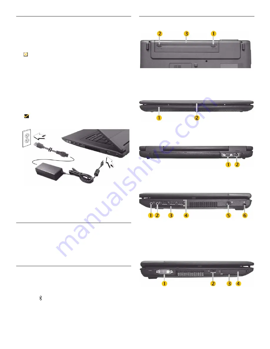
Views
*Smart card slot is a feature for X90Le; insert with electrical contacts facing
upwards.
*Express card slot accepts either ExpressCard/34 or ExpressCard/54 formats..
Bottom View
1
Battery lock
2
Battery release latch
3
Battery
Front View
1
System indicator lights
2
Release latch
Back View
1
VGA port
2
LAN RJ45
Right View
1
Line out/Headset out
4
USB port (3)
2
Microphone in
5
Power adapter input
3
Smart card slot*
6
Kensington lock slot
Left View
1
DVI port
2
USB port
3
SD card slot
4
Express card slot*


