


HDMI/HDBaseT Wiring
IMPORTANT! Wiring Guidelines
•
The use of patch panels, wall plates, cable extenders, kinks in cables, and
electrical or environmental interference can have an adverse effect on
HDMI or HDBaseT transmission limiting performance. Steps should be
taken to minimize these factors (or remove completely) during installation
for best results.
•
While similar in nature, the HDBaseT protocol is different than Ethernet and
voltages provided for PoH can be higher than those provided by PoE. For
this reason, never connect an HDBaseT link to an Ethernet router or switch
to avoid damaging the connected devices.
Wiring for HDBaseT follows the EIA T568B standard.
Pin 1 Pin 8
Wire colors shown follow EIA/TIA-568B standard.
Pin 1:
Pin 2:
Pin 3:
Pin 4:
Pin 5:
Pin 6:
Pin 7:
Pin 8:
White/Orange
Orange
White/Green
Blue
White/Blue
Green
White/Brown
Brown
Resolution Distances
The type of category cable used and the distance between the matrix and
receiver can restrict the available video resolution.
Refer to
Video Resolutions
in the
Specifications
table for the max distance
based on resolution.
IR Wiring
IR TX (Emitter) Wiring
Connection for IR TX (transmit) uses a 3.5mm (1/8in) mono plug.
Tip:
IR Signal
Sleeve: Ground (GND)
IR RX/Ext (Receiver) Wiring
Connection for IR RX (receive) uses a 3.5mm (1/8in) stereo jack that outputs
+5V DC to power the included IR receiver.
IMPORTANT!
3
rd
party IR receivers may require a different voltage, refer to the
documentation provided with the IR receiver before making any connections
to avoid damaging the device.
Tip:
Ring:
IR Signal
+5V DC
Sleeve: Ground (GND)
RS-232 Wiring
RS-232 Connection Guidelines
The following wiring diagram shows the pinouts for the extender set. While
not shown, connect the TX (transmit) to RX (receive) pins at the control
system or PC side of the cable. Most control systems and computers are
DTE where pin 2 is RX, this can vary from device to device. Refer to the
documentation for the connected device for pin functionally to ensure that the
correct connections can be made.
Pin 1:
Pin 2:
Pin 3:
Pin 4:
Pin 5:
Pin 6:
Pin 7:
Pin 8:
TX (Transmit)
RX (Receive)
-------
-------
GND (Ground)
Outside of DB9
female chassis port
shown.
-------
-------
-------
Pin 9: -------
5
9
8 7 6
4
3
2
1
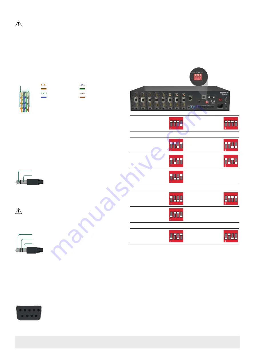
EDID Settings
EDIDs can be configured to resolve issues with video output on displays that
may not accept the maximum resolution available from the source.
•
When set to Smart EDID (default) the matrix will scan all selected displays
for the lowest resolution.
•
When EDID Copy or a direct EDID is being used, SmartEDID is turned Off.
•
Ensure that a display is connected and powered On to the selected output
before copying EDIDs or the copy will fail. When this occurs, EDID will be
set to 4K@30Hz 2ch.
•
Power to the matrix must be cycled (Off/On) after changing dip switches in
order for the setting to take effect.
Smart EDID - Display
Lowest Resolution - 2ch
(default)
1 2 3 4
ON
Front Panel, Web UI or
API EDID Control
1 2 3 4
ON
4K UHD
4K @60Hz 2ch No HDR
1 2 3 4
ON
4K @30Hz 7.1ch With
HDR
1 2 3 4
ON
4K @30Hz 5.1ch With
HDR
1 2 3 4
ON
4K @30Hz 2ch With
HDR
1 2 3 4
ON
4K @30Hz 8bit 2ch No
HDR
1 2 3 4
ON
1080p
1080p @60Hz 7.1ch
1 2 3 4
ON
1080p @60Hz 5.1ch
1 2 3 4
ON
1080p @60Hz 2ch
1 2 3 4
ON
Standard Video
1920x1200 2ch
1 2 3 4
ON
1920x1200 No Audio
1 2 3 4
ON
Copying EDIDs
1.
Set the EDID dipswitch to the
Front Panel, Web UI or API EDID Control
(all switches up).
2.
Reboot the matrix.
3.
Using the front navigation buttons, select the input port for the output.
Example: Input 2 for Output 2
4.
Once the output port indicator blinks, press and hold Enter for 5
seconds. An
OK
message of the display indicates that the copy was
successful, an
FL-2
indicates that the copy failed.
5.
Reboot the matrix.
Note:
EDID Copy feature is not available when Matrix in Smart EDID mode.
Copyright © 2016 WyreStorm Technologies |
wyrestorm.com
MX-0606-HDBT-H2 v2 | MX-0808-HDBT-H2 v2 Quickstart Guide | 160913
North America: 518-289-1294 | EMEA/ROW: 44 (0) 1793 230 343
3 of 4


