


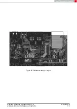


• Second layer is ground, except the antenna free area.
• Third layer is the supply layer, except antenna free area. Some routing is allowed, not
dividing the supply layer in to many or to small parts.
• Bottom layer is used for routing.
Figure 30: Close-up Schematic
Two variants of the Calypso are certified:
• Using the inside the module integrated PCB antenna. Not placing C1, C14 and C15,
but placing 0 Ohm for C13. C13 connects the RF_PAD, the radio signal from/toward
the transceiver, to the ANT_PAD, the connection to the inside the module integrated
antenna.
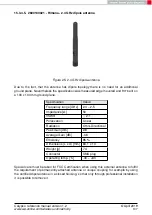
• Placing 22pF for C1, not placing C13, C14 and C15. Through C1 connecting with a 50
Ω
line a dipol antenna. For the certification the antenna from 15.3.4.5 was used with
peak gain of 2.8 dBi.
Special care must be taken when using an external antenna to fullfil the requirement for FCC
Certification of permanently attached antenna or unique coupling for example by using the
certified dipol antenna in a closed housing, so that only through professional installation it is
possible to remove it.
Calypso reference manual version 1.2
© April 2019
www.we-online.com/wireless-connectivity
112


