16
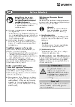
Attention!
Risk of property damage
■
The pressure can also cause the product to
flow out and cause the device to stick strongly
together.
¾
Never completely shut the air regulator
[2]
during use.
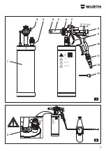
Setting compressed air consumption
■
Turn the air
supply
regulator
[11]
:
• Clockwise: Air flow reduces until it is completely
stopped.
• Anticlockwise: Airflow increases (higher con
-
sumption).
Note
During normal use, the air
supply
regu-
lator
[11]
must be completely open if
the pressure is between 3–4 bar.
It must be adjusted if the pressure is
above 4 bar.
Combined setting
Combined setting of the nozzle regulator
[8]
and
the air regulator
[2]
allows a smooth or rough
surface to be achieved as desired; and thus a finish
matching the original finish of the part being treated
can be achieved.
Water-based products
■
Turn the nozzle regulator
[8]
clockwise to a
maximum 10–12 mm. The nozzle needle is fully
opened and consequently maximum product
flow from the tank is achieved.
Smooth surface setting
■
Completely open the air vent regulator
[3]
(turn
clockwise). During use air flows from the tank
(reducing the pressure available in the tank) and
reduces the product quantity.
■
If spraying is not taking place, slowly turn the air
vent regulator
[3]
anticlockwise until the desired
product quantity is achieved.
■
Fully open air regulator
[2]
.
■
Set atomisation using air regulator
[2]
.
Rough surface setting
■
Slightly close air vent regulator
[3]
(anticlock
-
wise). As a result, the pressure in the tank
increases and with it the product quantity.
■
Slightly close air regulator
[2]
dependent on the
surface.
■
Set atomisation using air regulator
[2]
.
Attention!
Risk of property damage
■
The pressure can also cause the product to
flow out and cause the device to stick strongly
together.
¾
Never completely shut the air regulator
[2]
during use.
Combined setting
Combined setting of air vent regulator
[3]
and air
regulator
[2]
allows a smooth or rough surface to
be achieved as desired; and thus a finish matching
the original finish of the part being treated can be
achieved.
The air
supply
regulator
[11]
is in these cases set to
match the requirements of the operator.
Содержание 0891 110 640
Страница 3: ...10 12 mm AIR EXIT 3 II I 8 7 3 3 1 2 10 11 12 9 4 5 6 13...
Страница 4: ...4 5 5 6 7 4 4 3 3 3 2 2 2 1 1 1 III IV V 4 5 6 13...
Страница 82: ...82 GR W rth 3 3 1...
Страница 83: ...83 18 16 8 bar...
Страница 85: ...85 9 8 1 V 2 2 V 3 3 V 11 9 3 4 V 2 9 8 360 9 5 V 2 6 V 8 2 7 V 8 4 5 III 10 30 9 3 3 IV 4 5 13 5 6 V 2...
Страница 86: ...86 2 2 11 11 3 4 bar 4 bar 8 2 8 10 12 mm 3 3 2 2 3 2 2 2 3 2 11...
Страница 87: ...87 9 11 11 2 45 3...
Страница 138: ...138 BG W rth 3 3 1...
Страница 139: ...139 18 16 8 bar...
Страница 141: ...141 9 8 1 V 2 2 V 3 3 V 11 9 3 4 V 2 9 8 360 9 5 V 2 6 V 8 2 7 V 8 4 5 10 30 cm 9 3 3 V 4 5 13 5 6 V 2...
Страница 142: ...142 2 2 11 11 3 4 bar 4 bar 8 2 8 10 12 mm 3 3 2 2 3 2 2 2 3 2 11...
Страница 143: ...143 9 11 11 2 45 3...
Страница 166: ...166 RU W rth 3 3 1...
Страница 167: ...167 18 16 8...
Страница 169: ...169 2 2 V 3 3 V 11 9 3 4 V 2 9 8 360 9 5 V 2 6 V 8 2 7 V 8 4 5 III 10 30 9 3 3 IV 4 5 13 5 6 V 2 9 8 1 V...
Страница 170: ...170 2 2 11 11 3 4 4 8 2 8 10 12 3 3 2 2 3 2 2 2 3 2 11...
Страница 171: ...171 9 11 11 2 45 3...
Страница 173: ...173...
Страница 174: ...174...
Страница 175: ...175...

