background image

GENERAL

L4100, WSM

G-36

(EU)

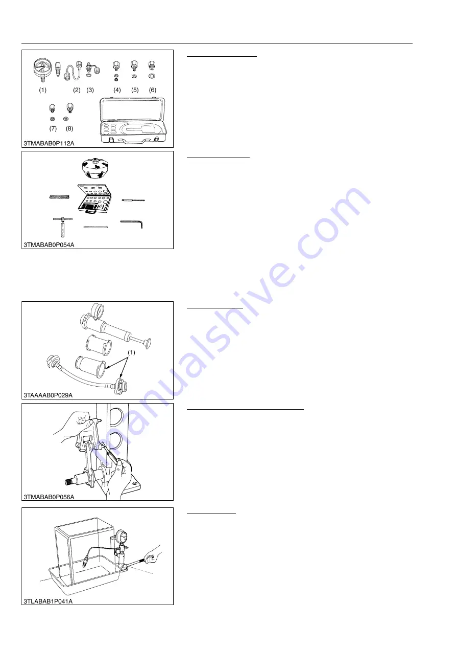
Oil Pressure Tester
Code No.

• 07916-32032

Application

• Use to measure lubricating oil pressure.

WSM000001GEG0015US0

Valve Seat Cutter
Code No.

• 07909-33102

Application

• Use to reseat valves.

Angle

• 0.79 rad (45 °)
• 0.26 rad (15 °)

Diameter

• 28.6 mm (1.13 in.)
• 31.6 mm (1.24 in.)
• 35.0 mm (1.38 in.)
• 38.0 mm (1.50 in.)
• 41.3 mm (1.63 in.)
• 50.8 mm (2.00 in.)

WSM000001GEG0016US0

Radiator Tester
Code No.

• 07909-31551

Application

• Use to check of radiator cap pressure, and leaks from cooling

system.

Remarks

• Adaptor (1) BANZAI Code No. RCT-2A-30S.

WSM000001GEG0017US0

Connecting Rod Alignment Tool
Code No.

• 07909-31661

Application

• Use to check the connecting rod alignment.

Applicable range

• Connecting rod big end I.D.

30 to 75 mm dia. (1.2 to 2.9 in. dia.)

• Connecting rod length

65.0 to 300 mm (2.56 to 11.8 in.)

WSM000001GEG0020US0

Nozzle Tester
Code No.

• 07909-31361

Application

• Use to check the fuel injection pressure and spray pattern of

nozzle.

Measuring range

• 0 to 50 MPa (0 to 500 kgf/cm

2

, 0 to 7200 psi)

WSM000001GEG0021US0

(1) Gauge
(2) Cable
(3) Threaded Joint
(4) Adaptor 

1

(5) Adaptor 

2

(6) Adaptor 

3

(7) Adaptor 

4

(8) Adaptor 

5

(1) Adaptor

KiSC issued 08, 2012 A 

Содержание Kubota L4100

Страница 1: ...L4100 WORKSHOP MANUAL TRACTOR KiSC issued 08 2012 A...

Страница 2: ...nue with the subsequent sections make sure that you read this section Refer to the latest version of Workshop Manual Code No 9Y021 01870 9Y021 18200 for the diesel engine tractor mechanism that this w...

Страница 3: ...I INFORMATION KiSC issued 08 2012 A...

Страница 4: ...CONTENTS 1 SAFETY FIRST I 1 2 SAFETY DECALS I 4 3 SPECIFICATIONS I 6 4 TRAVELING SPEEDS I 7 5 DIMENSIONS I 8 INFORMATION KiSC issued 08 2012 A...

Страница 5: ...isengaged positions Do not start the engine when you stay on the ground Start the engine only from operator s seat WSM000001INI0011US0 SAFETY FIRST This symbol the industry s Safety Alert Symbol is us...

Страница 6: ...u disconnect hydraulic or fuel lines Tighten all connections before you apply the pressure Do not open a fuel system under high pressure The fluid under high pressure that stays in fuel lines can caus...

Страница 7: ...ons when you discard oil fuel coolant electrolyte and other dangerous waste WSM000001INI0007US1 PREVENT ACID BURNS Keep electrolyte away from your eyes hands and clothing Sulfuric acid in battery elec...

Страница 8: ...ing safety decals pictorial safety labels are installed on the machine If a decal becomes damaged illegible or is not on the machine replace it The decal part number is listed in the parts list WSM000...

Страница 9: ...INFORMATION L4100 WSM I 5 EU 9Y1210278INI0002US0 KiSC issued 08 2012 A...

Страница 10: ...11 U S gals 8 8 Imp gals Dimensions Overall length without 3P 3005 mm 118 3 in Overall width min tread 1490 mm 58 86 in Overall height with ROPS 2525 mm 99 41 in 2378 mm 93 62 in Wheel base 1845 mm 72...

Страница 11: ...specifications without notice 9Y1210278INI0004US0 Model L4100 Tire size Rear 13 6 26 Shuttle shift lever Range gear shift lever Main gear shift lever km h mph Forward Low 1 1 4 0 87 2 1 9 1 2 3 3 1 1...

Страница 12: ...INFORMATION L4100 WSM I 8 EU 5 DIMENSIONS Rear mount type ROPS 9Y1210278INI0005US0 KiSC issued 08 2012 A...

Страница 13: ...INFORMATION L4100 WSM I 9 EU Mid mount type ROPS 9Y1210278INI0006US0 KiSC issued 08 2012 A...

Страница 14: ...G GENERAL KiSC issued 08 2012 A...

Страница 15: ...NCE G 13 7 CHECK AND MAINTENANCE G 15 1 DAILY CHECK G 15 2 CHECK POINTS OF INITIAL 50 HOURS G 15 3 CHECK POINTS OF EVERY 50 HOURS G 18 4 CHECK POINTS OF EVERY 100 HOURS G 21 5 CHECK POINTS OF EVERY 20...

Страница 16: ...A distributor always specify engine serial number tractor serial number and hour meter reading 9Y1210278GEG0005US0 1 Tractor Identification Plate 2 Tractor Serial Number 3 Engine Serial Number 4 ROPS...

Страница 17: ...CYLINDER NUMBER You can see the cylinder numbers of KUBOTA diesel engine in the figure The sequence of cylinder numbers is No 1 No 2 No 3 and No 4 and it starts from the gear case side WSM000001GEG005...

Страница 18: ...OTA genuine parts for parts replacement to maintain machine performance and to assure safety Gaskets and O rings must be replaced during reassembly Apply grease to new O rings or oil seals before asse...

Страница 19: ...e Do not attempt to modify or remodel any electrical parts and wiring When removing the battery cables disconnect the negative cable first When installing the battery cables connect the positive cable...

Страница 20: ...ired WSM000001GEG0068US1 In installing a part take care not to get wiring caught by it WSM000001GEG0069US1 After installing wiring check protection of terminals and clamped condition of wiring only co...

Страница 21: ...ng the battery remove it from the machine Before recharging remove cell caps Do recharging in a well ventilated place where there is no open flame nearby as hydrogen gas and oxygen are formed WSM00000...

Страница 22: ...male connector being too open WSM000001GEG0076US1 Make certain plastic cover is large enough to cover whole connector WSM000001GEG0077US1 5 HANDLING OF CIRCUIT TESTER Use tester correctly following ma...

Страница 23: ...symbol of shows color with stripe s An example Red stripe on white color W R WSM000001GEG0079US0 Color of wiring Color code Black B Brown Br Green G Gray Gy or Gr Blue L Light Green Lg Orange Or Pink...

Страница 24: ...mp qts Engine oil Refer to next page Below 0 C 32 F SAE10W 10W 30 or 15W 40 0 to 25 C 32 to 77 F SAE20 10W 30 or 15W 40 Above 25 C 77 F SAE30 10W 30 or 15W 40 4 Transmission case 40 0 L 10 6 U S gals...

Страница 25: ...mended No 2 D is a distillate fuel of lower volatility for engine in industrial and heavy mobile service SAE J313 JUB87 Since this engine adopts EPA Tier 4 and Interim Tier 4 standards the use of low...

Страница 26: ...4 6 29 to 33 32 to 34 3 2 to 3 5 24 to 25 48 to 55 4 9 to 5 7 36 to 41 40 to 44 4 0 to 4 5 29 to 32 61 to 70 6 2 to 7 2 45 to 52 M12 63 to 72 6 4 to 7 4 47 to 53 78 to 90 7 9 to 9 2 58 to 66 63 to 72...

Страница 27: ...1 to 11 6 16 3 to 19 7 1 66 to 2 01 12 0 to 14 6 5 16 23 1 to 27 7 2 35 to 2 83 17 0 to 20 5 33 to 39 3 4 to 4 0 24 to 29 3 8 48 to 56 4 9 to 5 8 35 0 to 42 0 61 to 73 6 3 to 7 4 45 to 54 1 2 110 to 1...

Страница 28: ...100 hr G 24 Replace every 2 years G 29 10 Fuel filter element Clean every 100 hr G 25 Replace every 400 hr G 27 11 Parking brake cable Adjust every 100 hr G 25 Replace every 2 years G 29 12 Engine oil...

Страница 29: ...ck the battery condition by reading the indicator annually 9Y1210278GEG0076US0 23 Fuel injection nozzle injection pressure Check every 1500 hr G 29 24 Injection pump Check every 3000 hr 1 S15 25 Cooli...

Страница 30: ...e sitting in the operator s seat 1 Check the brake pedals and clutch pedal 2 Check the parking brake 3 Check the steering wheel Turning the key switch 1 Check the performance of the Easy Checker light...

Страница 31: ...sure to stop the engine before changing oil filter cartridge 1 Allow engine to cool down sufficiently oil can be hot and can burn 1 Remove the engine oil filter cartridge 1 2 Put a film of clean engi...

Страница 32: ...g surface then tighten it by hand an additional 1 2 turn only 7 Fill with the new KUBOTA SUPER UDT fluid up to the upper notch on the dipstick 8 After running the engine for a few minutes stop the eng...

Страница 33: ...lever to OFF position 3 Shift the range gear shift lever to L H or R position 4 Depress the clutch pedal fully 5 Turn the key to START position 6 The engine must not crank 7 If it cranks consult your...

Страница 34: ...neutral position 5 Turn the key to START position 6 The engine must not crank Q Test 3 Switch for the operator s seat 1 Sit on the operator s seat 2 Start the engine 3 Engage the PTO clutch control s...

Страница 35: ...ase fittings more often When applying a grease to the front axle support remove the breather plug and apply a grease until grease overflows from breather plug After greasing reinstall the plug 9Y12102...

Страница 36: ...nstalled battery is of non refillable type If the indicator turns white do not charge the battery but replace it with new one 1 Mishandling the battery shortens the service life and adds to maintenanc...

Страница 37: ...hion 2 A boost charge is only for emergencies It will partially charge the battery at a high rate and in a short time When using a boost charged battery it is necessary to recharge the battery as earl...

Страница 38: ...measure free travel A at top of pedal stroke 3 If the measurement is not within the factory specifications loosen the lock nut 1 and turn the turnbuckle 2 to adjust it within the factory specification...

Страница 39: ...with filter element removed Be sure to refit the dust cup with the arrow on the rear of cover upright If the dust cup is improperly fitted evacuator valve will not function and dust will adhere to th...

Страница 40: ...CAUTION Stop the engine and chock the wheels before checking parking brake 1 Raise the parking brake lever to the parking position while counting the ratchet sound made by the parking brake lever 2 I...

Страница 41: ...nap ring 3 2 Loosen the tie rod lock nut 1 3 Turn the outer tube to adjust the tie rod length until the proper toe in measurement is obtained 4 Retighten the tie rod lock nut 1 5 Attach the snap ring...

Страница 42: ...2 Don t stop the engine suddenly but stop it after about 5 minutes of unloaded idling 3 Keep yourself well away from the machine for further 10 minutes or while the steam blown out 4 Checking that the...

Страница 43: ...w minutes to prevent damage to the transmission Do not mix different brands oil together 9Y1210278GEG0072US0 Changing Front Axle Case Oil 1 Place the oil pans underneath the front axle case 2 Remove t...

Страница 44: ...ng Injection Pump See page 1 S15 9Y1210278GEG0037US0 11 CHECK POINT OF EVERY 1 YEAR Replacing Air Cleaner Element See page G 24 9Y1210278GEG0038US0 12 CHECK POINTS OF EVERY 2 YEARS Replacing Fuel Hose...

Страница 45: ...ll with clean water and anti freeze until the coolant level is just below the radiator cap Install the radiator cap 1 securely 7 Fill with coolant up to the FULL mark of recovery tank 8 Start and oper...

Страница 46: ...ulations when disposing of antifreeze If it freezes coolant can damage the cylinders and radiator If the ambient temperature falls below 0 C 32 F or before a long term storage let out cooling water co...

Страница 47: ...ay have different additive components and the engine may fail to perform as specified NOTE The above date represent industry standards that necessitate a minimum glycol content in the concentrates ant...

Страница 48: ...ent cock 1 after 30 seconds IMPORTANT Always close the air vent cock 1 except for bleeding fuel lines Otherwise Engine runs irregularly or stalls frequently 9Y1210278GEG0045US0 Draining Clutch Housing...

Страница 49: ...eplace with a new one of the same capacity 9Y1210278GEG0047US0 Replacing Light Bulb 1 Head lights and rear combination lights Take the bulb out of the light body and replace with a new one 2 Other lig...

Страница 50: ...Ring Tool Code No 07909 32121 Application Use exclusively for removing or installing the piston ring with ease WSM000001GEG0013US0 Diesel Engine Compression Tester for Injection Nozzle Code No 07909...

Страница 51: ...from cooling system Remarks Adaptor 1 BANZAI Code No RCT 2A 30S WSM000001GEG0017US0 Connecting Rod Alignment Tool Code No 07909 31661 Application Use to check the connecting rod alignment Applicable...

Страница 52: ...d tighten the mounting nut of fan drive pulley M00000003GEG0062US1 Auxiliary Socket for Fixing Crankshaft Sleeve Application To fix the crankshaft sleeve of the diesel engine 9Y1210278GEG0004US0 A 100...

Страница 53: ...25 mm dia 0 98 in dia H 7 70 to 8 00 mm dia 0 304 to 0 314 in dia I 5 mm 0 2 in J 20 mm dia 0 79 in dia K 13 5 to 13 8 mm dia 0 532 to 0 543 in dia L 8 90 to 9 10 mm 0 351 to 0 358 in C1 Chamfer 1 0...

Страница 54: ...in radius D 10 mm 0 39 in E 20 mm 0 79 in F 20 mm dia 0 79 in dia G 64 80 to 64 90 mm dia 2 552 to 2 555 in dia H 59 80 to 59 90 mm dia 2 355 to 2 358 in dia A 130 mm 5 12 in B 72 mm 2 8 in C 40 mm ra...

Страница 55: ...0 Clutch Center Tool For B and L Series Tractors Application The clutch center tool can be used for all B and L series tractors with a diaphragm clutch by changing tip guides Center piece diameter is...

Страница 56: ...ocking Tool Code No 07916 55311 Application Use for preventing the shaft from turning when removing or tighten a bevel pinion shaft staking nut WSM000001GEG0039US0 Relief Valve Setting Pressure Adapto...

Страница 57: ...mensions S T and number of holes M b Direction of pipe I 9Y1210278GEG0049US0 A 22 mm 0 872 in H 10 mm dia 0 39 in dia O 61 5 mm 2 42 in B 11 mm 0 437 in I G 3 8 P 24 mm 0 94 in C 24 mm dia 0 94 in dia...

Страница 58: ...A 40 0 mm dia 1 57 in dia B 26 0 mm dia 1 02 in dia C 36 0 mm dia 1 42 in dia D 200 mm 7 87 in E 40 0 mm 1 57 in F 250 mm 9 84 in G 10 0 mm 0 39 in H 22 mm dia 0 87 in dia I 25 mm dia 0 98 in dia J 25...

Страница 59: ...5 161 in 49 7 to 49 9 mm 1 957 to 1 964 in B 24 5 to 25 5 mm 0 965 to 1 00 in 21 5 to 22 5 mm 0 847 to 0 885 in C 40 0 mm 1 57 in 40 0 mm 1 57 in D 32 0 mm 1 26 in 32 0 mm 1 26 in E 49 70 to 49 90 mm...

Страница 60: ...nd adjusting the draft control rod by using the draft control test bar about 50 kg 490 N 110 lbf of weight is needed 9Y1210278GEG0086US0 A 1000 mm 39 37 in B 25 mm 0 984 in C 140 mm 5 51 in D 200 mm 7...

Страница 61: ...N 21 947 to 21 960 mm dia 0 8641 to 0 8646 in dia D 0 52 rad 30 O 28 mm 1 10 in E 46 950 to 46 975 mm dia 1 8484 to 1 8494 in dia P 29 mm 1 14 in F 43 934 to 43 950 mm dia 1 7297 to 1 7303 in dia Q 5...

Страница 62: ...dia 1 38 in dia T 60 mm dia 2 36 in dia G 60 mm dia 2 36 in dia U 46 950 to 46 975 mm dia 1 8484 to 1 8494 in dia H 37 mm 1 46 in V 44 950 to 44 975 mm dia 1 7697 to 1 7707 in dia I 21 947 to 21 960 m...

Страница 63: ...re removing a wheel Do not work under any hydraulically supported devices They can settle suddenly leak down or be accidentally lowered If necessary to work under tractor or any machine elements for s...

Страница 64: ...maged When re fitting or adjusting a wheel tighten the bolts to the following torques then recheck after driving the tractor 200 m 200 yards and 10 times of shuttle movement by 5 m 5 yards and thereaf...

Страница 65: ...de solution do not pour water over calcium chloride since this results in chemical reaction which will cause high temperature Instead add a small amount of calcium chloride to the water at a time unti...

Страница 66: ...mpleted reset the air valve and pump air into the tire to the specified pressure Weight of Calcium Chloride Solution Filling 75 of Full Capacity of a Tire 9Y1210278GEG0082US0 Tire sizes 13 6 26 Slush...

Страница 67: ...1 ENGINE KiSC issued 08 2012 A...

Страница 68: ...CONTENTS 1 LUBRICATING SYSTEM 1 M1 2 COOLING SYSTEM 1 M2 3 FUEL SYSTEM 1 M3 MECHANISM KiSC issued 08 2012 A...

Страница 69: ...lter cartridge where it is further filtered Then the oil is forced to crankshaft 7 connecting rods 16 idle gear 6 governor shaft 5 camshaft 14 and rocker arm shaft 3 to lubricate each part thorough th...

Страница 70: ...losed and the coolant is allowed to flow through the bypass pipe and to circulate in the engine When the temperature exceeds the thermostat valve opening level the thermostat fully opens itself to pre...

Страница 71: ...er passing through the fuel filter 7 The fuel camshaft actuates the injection pump and force feeds fuel to the injection nozzle 2 through the injection pipe 3 Fuel is then sprayed through the nozzle i...

Страница 72: ...S16 2 PREPARATION 1 S17 1 Separating Engine and Clutch Housing 1 S17 2 Separation Engine from Front Axle Frame 1 S24 3 DISASSEMBLING AND ASSEMBLING 1 S25 1 Cylinder Head and Valves 1 S25 2 Timing Gear...

Страница 73: ...ng Repair or replace Compression leak from cylinder Replace head gasket tighten cylinder head screw glow plug and nozzle holder 1 S27 1 S28 Improper valve timing Correct or replace timing gear 1 S46 P...

Страница 74: ...Repair or replace nozzle 1 S15 Deficient nozzle injection Repair or replace nozzle 1 S15 Compression leak Replace head gasket tighten cylinder head bolt glow plug and nozzle holder 1 S27 1 S28 Excess...

Страница 75: ...tive Repair or replace 1 S33 1 S57 High Oil Pressure Different type of oil Use specified type of oil G 9 Relief valve defective Replace Engine Overheated Engine oil insufficient Replenish G 9 Fan belt...

Страница 76: ...3161 in 0 10 mm 0 0039 in Valve Seat Width 2 12 mm 0 0835 in Valve Spring Tilt Free length Setting Load Setting Length 41 7 to 42 2 mm 1 65 to 1 66 in 117 6 N 35 0 mm 12 0 kgf 35 0 mm 26 4 lbf 1 3780...

Страница 77: ...in 0 01 mm 0 0004 in Idle Gear Shaft to Idle Gear Bushing Clearance O D I D 0 025 to 0 066 mm 0 00099 to 0 0025 in 37 959 to 37 975 mm 1 4945 to 1 4950 in 38 000 to 38 025 mm 1 4961 to 1 4970 in 0 10...

Страница 78: ...n Item Factory Specification Allowable Limit Item Factory Specification Allowable Limit Piston Pin Bore I D 25 000 to 25 013 mm 0 98426 to 0 98476 in 25 05 mm 0 9862 in Piston Pin to Small End Bushing...

Страница 79: ...o 2 3637 in 0 20 mm 0 0079 in Crankshaft Bearing 1 Dimension 59 921 to 59 940 mm 2 3591 to 2 3598 in Crankshaft to Crankshaft Bearing 2 Crankshaft Journal Crankshaft Bearing 2 Clearance O D I D 0 0400...

Страница 80: ...unting stud bolt 40 to 49 4 0 to 5 0 29 to 36 Clutch mounting screw 24 to 27 2 4 to 2 8 18 to 20 Muffler mounting screw 32 to 39 3 2 to 4 0 24 to 28 Front axle frame mounting M10 screw 61 to 70 6 2 to...

Страница 81: ...6 for each cylinder 8 If the measurement is below the allowable limit apply a small amount of oil to the cylinder wall through the nozzle hole and measure the compression pressure again 9 If the compr...

Страница 82: ...arking line on the flywheel is just for No 1 cylinder There is no TC marking for the other cylinders No 1 piston comes to the T D C position when the TC marking is aligned with center of timing window...

Страница 83: ...5 Remove the cylinder head and measure the thickness of the fuses 6 If the measurement is not within the factory specifications check the oil clearance between the crankpin and bearing and between th...

Страница 84: ...specified torque 9Y1210278ENS0007US0 5 Fan Belt Fan Belt Tension 1 Measure the deflection A depressing the belt halfway between the fan drive pulley and alternator pulley at specified force 68 6 N 7...

Страница 85: ...10278ENS0008US0 Radiator Cap Air Leakage CAUTION When removing the radiator cap wait at least ten minutes after the engine has stopped and cooled down Otherwise hot water way gush out scalding nearby...

Страница 86: ...T 2S 30S and raise the water pressure to the specified pressure 3 Check the radiator for water leaks 4 If any leaks are detected replace the radiator or repair with the radiator cement Of the water le...

Страница 87: ...g add or remove the shim to adjust Injection Timing NOTE The sealant is applied to both sides of the soft metal gasket shim The liquid gasket is not required for assembling Shims are available in thic...

Страница 88: ...ndle to measure the pressure at which fuel begins jetting out from the nozzle 3 If the measurement is not within the factory specifications replace the adjusting washer 1 in the nozzle holder to adjus...

Страница 89: ...install the drain plugs 1 When refilling Fill the engine oil up to the upper line on the dipstick 3 IMPORTANT Never mix two different type of oil Use the proper SAE Engine Oil according to ambient tem...

Страница 90: ...vent damage to the transmission Do not mix different brands oil together 9Y1210278ENS0109US0 Draining Coolant CAUTION Never remove the radiator cap until coolant temperature is well below its boiling...

Страница 91: ...cable 1 2 Disconnect the connector to head light 3 horn 2 and the head light wiring 3 Remove bonnet 4 and side covers 5 on both sides 4 Remove the front cover 6 9Y1210278ENS0019US0 1 Battery Negative...

Страница 92: ...ne stop solenoid relay 10 and 4P connector to glow relay 9 8 Disconnect the fuel tank wiring 11 9 Remove the rear bonnet 3 When reassembling 9Y1210278ENS0020US0 Tightening torque Steering wheel mounti...

Страница 93: ...et hose 6 I PTO delivery pipe 4 and 3P delivery pipe 3 When reassembling 9Y1210278ENS0021US0 Tightening torque Independent PTO delivery pipe joint bolt 35 to 39 N m 3 5 to 4 0 kgf m 26 to 28 lbf ft Po...

Страница 94: ...torque Starter B terminal mounting nut 7 9 to 9 8 N m 0 80 to 1 0 kgf m 5 8 to 7 2 lbf ft 1 1P Connector Battery 2 Flasher Unit Connector 3 Slow Blow Fuse Box 4 2P Connector Alternator 5 Wiring Alter...

Страница 95: ...upport plates connecting steering support and rear bonnet support 3 Remove the engine and clutch housing mounting screws and nuts 4 Separate the engine and clutch housing When reassembling Apply greas...

Страница 96: ...s 2 3 Remove rear bonnet support mounting screws 3 on both sides 4 Remove fuel tank 1 together with rear bonnet support 6 and shutter plate 5 9Y1210278ENS0027US0 Radiator Hose Recovery Tank Muffler 1...

Страница 97: ...er Head and Valves External Components 1 Set the engine to the disassembling stand 2 Remove the cooling fan 1 3 Remove the alternator 3 and fan belt 2 4 Remove the starter motor 4 IMPORTANT After reas...

Страница 98: ...S0032US0 Hydraulic Pump and Other External Components 1 Remove hydraulic pump mounting screws and detach hydraulic pump 1 2 Remove the accelerator cable 2 hour meter flexible cable 3 9Y1210278ENS0033U...

Страница 99: ...tion nozzle gasket must be changed when the injection nozzle is removed for cleaning or for service 9Y1210278ENS0096US0 Rocker Arm and Push Rod 1 Remove the rocker arm bracket screws 2 Detach the rock...

Страница 100: ...around them IMPORTANT Do not change the combination of tappet and tappet guide 9Y1210278ENS0037US0 Valves 1 Remove the valve caps 2 2 Remove the valve spring collet 3 pushing the valve spring retaine...

Страница 101: ...idling body gasket 6 with a new one Before fitting the stop lever 3 to the gear case install the solenoid guide 5 first into position Then attach the stop lever and use it to see if it functions well...

Страница 102: ...3 Using the specific tool 1 undo the large governor spring 2 from the fork lever 3 4 Using the specific tool 1 undo the small governor spring 4 from the fork lever 3 5 Set the speed control lever 5 a...

Страница 103: ...t deformed permanently Using the specific tool 1 hook the large governor spring 2 onto the fork lever 3 Make sure both the governor springs 2 4 are tight on the fork lever 3 Apply and tighten up the t...

Страница 104: ...case gasket apply a non drying adhesive 9Y1210278ENS0042US0 Crankshaft Oil Slinger 1 Remove the crankshaft collar 3 2 Remove the O ring 2 3 Detach the crankshaft oil slinger 1 When reassembling Inser...

Страница 105: ...ssembling After installation check to see that the fork lever 1 1 and 2 2 are fixed to the fork lever shaft and that they can turn smoothly in the holder 5 9Y1210278ENS0047US0 Oil Pump 1 Remove the oi...

Страница 106: ...oil pan gasket 2 To avoid uneven tightening tighten oil pan mounting screws in diagonal order from the center For oil pan without oil pan gasket IMPORTANT Scrape off the old liquid gasket completely...

Страница 107: ...piston to top dead center 4 Draw out the piston upward by lightly tapping it from the bottom of the crankcase with the grip of a hammer 5 Draw out the other piston in the same method as above To be c...

Страница 108: ...direction as shown in the figure Carefully insert the pistons using a piston ring compressor 6 When inserting the piston in place be careful not to get the molybdenum disulfide coating torn off its sk...

Страница 109: ...oil ring 6 onto the piston 2 place the expander joint 10 on the opposite side of the oil ring gap 11 Apply engine oil to the piston pin When installing the piston pin 1 immerse the piston 2 in 80 C 1...

Страница 110: ...move it IMPORTANT The length of inside screws 6 and outside screws 3 are different Do not take a mistake using inside screws and outside screws When reassembling Fit the bearing case gasket 1 and the...

Страница 111: ...ring 2 2 Remove the main bearing case 1 2 and 3 When reassembling Clean the oil passage in the main bearing case Apply clean engine oil on the bearings Install the main bearing case assemblies in the...

Страница 112: ...278ENS0058US0 6 Injection Nozzle Nozzle Holder 1 Secure the nozzle retaining nut 7 with a vise 2 Remove the nozzle holder 1 and take out parts inside When reassembling Assemble the nozzle in clean fue...

Страница 113: ...he top clearance be sure to assemble the cylinder head with a new cylinder head gasket 9Y1210278ENS0006US0 Cylinder Head Surface Flatness 1 Clean the cylinder head surface 2 Place a straightedge on th...

Страница 114: ...9Y1210278ENS0062US0 Clearance between Valve Stem and Valve Guide 1 Remove carbon from the valve guide section 2 Measure the valve stem O D with an outside micrometer 3 Measure the valve guide I D wit...

Страница 115: ...1210278ENS0064US0 Valve Seating 1 Coat the valve face lightly with prussian blue and put the valve on its seat to check the contact 2 If the valve does not seat all the way around the valve seat or th...

Страница 116: ...ound between the valve face and valve seat and fit them with valve lapping tool 4 Check the valve seating with prussian blue The valve seating surface should show good contact all the way around 9Y121...

Страница 117: ...and Rocker Arm Shaft 1 Measure the rocker arm shaft O D with an outside micrometer 2 Measure the rocker arm I D with an inside micrometer and then calculate the oil clearance 3 If the oil clearance e...

Страница 118: ...learance is proper replace the gear 9Y1210278ENS0126US0 Push rod alignment Allowable limit 0 25 mm 0 0098 in Oil Clearance between tappet and tappet guide bore Factory specification 0 020 to 0 062 mm...

Страница 119: ...the allowable limit replace the idle gear shaft 9Y1210278ENS0074US0 Replacing Idle Gear Bushing When removing 1 Press out the used idle gear bushing using an idle gear bushing replacing tool When inst...

Страница 120: ...eeds the allowable limit replace the camshaft 9Y1210278ENS0077US0 Balancer Shaft Side Clearance 1 Set a dial indicator with tip on the balancer shaft 2 Measure the side clearance by moving the balance...

Страница 121: ...0 051 to 0 132 mm 0 00201 to 0 00520 in Allowable limit 0 20 mm 0 0079 in Balancer shaft journal 1 O D Factory specification 43 934 to 43 950 mm 1 72969 to 1 73032 in Balancer shaft bearing 1 I D Fact...

Страница 122: ...Rod Small End Bushing When removing 1 Press out the used small end bushing using a connecting rod small end bushing replacing tool When installing 1 Clean a new connecting rod small end bushing and b...

Страница 123: ...iston pin into the connecting rod 2 Install the connecting rod on the connecting rod alignment tool 3 Put a gauge over the piston pin and move it against the face plate 4 If the gauge does not fit squ...

Страница 124: ...nals 2 Set a dial indicator with its tip on the intermediate journal 3 Measure the crankshaft alignment 4 If the measurement exceeds the allowable limit replace the crankshaft 9Y1210278ENS0085US0 Cran...

Страница 125: ...move the crankshaft while the connecting rod screws are tightened Reference Undersize dimensions of crankpin 9Y1210278ENS0086US0 Oil clearance between crankpin and crankpin bearing Factory specificati...

Страница 126: ...tool press in a new bearing 1 2 so that its seam 1 directs toward the exhaust manifold side 9Y1210278ENS0114US0 Oil clearance between crankshaft journal and crankshaft bearing 1 Factory specification...

Страница 127: ...htened Reference Undersize dimensions of crankshaft journal 9Y1210278ENS0089US0 Oil clearance between crankshaft and crankshaft bearing 2 Factory specification 0 0400 to 0 104 mm 0 00158 to 0 00409 in...

Страница 128: ...the cylinder at the six positions see figure with a cylinder gauge to find the maximum and minimum I D s 2 Get the difference Maximum wear between the maximum and the minimum I D s 3 If the wear excee...

Страница 129: ...face with grease 2 Install the cover and tighten the screws 3 Remove the cover carefully and measure the width of the press gauge with a sheet of gauge 4 If the clearance exceeds the factory specific...

Страница 130: ...2 CLUTCH KiSC issued 08 2012 A...

Страница 131: ...CONTENTS 1 STRUCTURE 2 M1 1 TRAVELING CLUTCH 2 M1 2 HYDRAULIC PTO CLUTCH 2 M1 MECHANISM KiSC issued 08 2012 A...

Страница 132: ...0 2 HYDRAULIC PTO CLUTCH Hydraulic multiple disk clutch is used for tractor with independent PTO PTO is controlled by PTO clutch pack 2 activated by PTO clutch valve and independent of the driving sys...

Страница 133: ...t at the DISENGAGED position 9Y1210278CLM0006US0 Oil Flow The oil adjusted the pressure by the regulator valve flows into the PTO clutch valve 2 When the PTO lever is at the DISENGAGED position the oi...

Страница 134: ...turned to B position then the oil from the regulator valve is stopped by the spool 2 and the oil in the PTO clutch pack and accumulator is drained into the transmission case Thus the piston 4 is pushe...

Страница 135: ...ING 2 S5 1 CHECKING AND AJUSTING 2 S5 2 PREPARATION 2 S6 1 Travelling Clutch 2 S6 2 PTO Clutch 2 S12 3 PTO Clutch Valve 2 S14 3 DISASSEMBLING AND ASSEMBLING 2 S15 1 Traveling Clutch 2 S15 2 PTO Clutch...

Страница 136: ...e 2 S15 Diaphragm spring weaken or broken Replace 2 S15 Chattering Grease or oil on clutch disc facing Replace 2 S15 Clutch disc or pressure plate warped Replace 2 S15 Clutch disc boss spline worn or...

Страница 137: ...lace 2 S18 PTO Shaft Does Not Rotate PTO clutch malfunctioning Repair or replace 2 S17 PTO coupling left behind Install PTO Clutch Operating Pressure is Low Transmission oil improper or insufficient R...

Страница 138: ...Specification Allowable Limit PTO Clutch Valve Condition Engine Speed Idling Oil Temperature 40 to 60 C 104 to 140 F Relief Valve Setting Pressure 2 25 to 2 45 MPa 23 0 to 25 0 kgf cm2 327 to 356 psi...

Страница 139: ...bolt 40 to 49 4 0 to 5 0 29 to 36 3P delivery pipe joint bolt 49 to 69 5 0 to 7 0 37 to 50 Main gear shift lever base mounting screw 24 to 27 2 4 to 2 8 18 to 20 Mid case and transmission case mountin...

Страница 140: ...Start the engine and measure the pressure 5 For adjustment use the reducing valve adjuster 3 of the regulator valve 5 IMPORTANT Do not connect the universal joint of the implement to the tractor PTO s...

Страница 141: ...efilling Fill up new oil from the oil filling port 3 up to the upper line of the oil level gauge 4 After running the engine for few minutes stop it and check the oil level again add oil to prescribed...

Страница 142: ...able 1 2 Disconnect the connector to head light 3 horn 2 and the head light wiring 3 Remove bonnet 4 and side covers 5 on both sides 4 Remove the front cover 6 9Y1210278ENS0019US0 1 Battery Negative C...

Страница 143: ...e stop solenoid relay 10 and 4P connector to glow relay 9 8 Disconnect the fuel tank wiring 11 9 Remove the rear bonnet 3 When reassembling 9Y1210278ENS0020US0 Tightening torque Steering wheel mountin...

Страница 144: ...et hose 6 I PTO delivery pipe 4 and 3P delivery pipe 3 When reassembling 9Y1210278ENS0021US0 Tightening torque Independent PTO delivery pipe joint bolt 35 to 39 N m 3 5 to 4 0 kgf m 26 to 28 lbf ft Po...

Страница 145: ...torque Starter B terminal mounting nut 7 9 to 9 8 N m 0 80 to 1 0 kgf m 5 8 to 7 2 lbf ft 1 1P Connector Battery 2 Flasher Unit Connector 3 Slow Blow Fuse Box 4 2P Connector Alternator 5 Wiring Alter...

Страница 146: ...upport plates connecting steering support and rear bonnet support 3 Remove the engine and clutch housing mounting screws and nuts 4 Separate the engine and clutch housing When reassembling Apply greas...

Страница 147: ...suction pipe 1 4 2 Remove oil filter bracket 3 together with oil filter 8 3 Remove hydraulic block 7 together with return pipe 6 4 Remove 3P delivery pipe 2 I PTO delivery pipe 5 5 Remove the brake co...

Страница 148: ...2 When reassembling Replace the gasket with a new one Apply liquid gasket Three Bond 1206C or equivalent to joint face of the clutch housing and mid case 9Y1210278CLS0014US0 Tightening torque Main ge...

Страница 149: ...prevent damage to the transmission Do not mix different brands oil together 9Y1210278ENS0109US0 Hose and Pipes 1 Remove the suction hose 1 2 Remove the PTO delivery pipe 2 and 3P delivery pipe 2 3 3...

Страница 150: ...th the clutch center tool When reassembling Direct the shorter end of the clutch disc boss toward the flywheel Apply molybdenum disulphide Three Bond 1901 or equivalent to the splines of clutch disc b...

Страница 151: ...remove the release fork 1 When reassembling Make sure the direction of the release fork 1 is correct Inject grease to the release hub 4 Be sure to set the snap pins 6 on both sides 9Y1210278CLS0018US...

Страница 152: ...unt of transmission fluid to the O ring Install oil pipe 2 to the side hole of PTO clutch holder 6 firmly 9Y1210278CLS0019US0 Tightening torque PTO clutch valve mounting screw 24 to 27 N m 2 4 to 2 8...

Страница 153: ...is thicker than the steel plates Assemble the plug rubbers portion of the three steel plates 6 10 and 12 are same positions while assembling them Refer to figure below Apply enough transmission fluid...

Страница 154: ...s 8 9Y1210278CLS0022US0 Brake Plate 1 Remove the brake plate mounting screws 3 and then take out the brake plate 4 and the springs 2 When reassembling Apply liquid lock Three Bond 1372 or equivalent t...

Страница 155: ...024US0 3 PTO Clutch Valve Clutch Valve Lever Arm 1 Make a marks on the spool and the lever arm 2 2 Draw out the lever arm 2 by the bearing puller after removing the external snap ring 3 When reassembl...

Страница 156: ...210278CLS0026US0 4 SERVICING 1 Traveling Clutch Backlash between Clutch Disc Boss and Shaft 1 Mount the PTO clutch disc to the 16T gear shaft 2 Hold the gear 16T gear shaft so that it does not turn 3...

Страница 157: ...ling parts except clutch disc with a suitable cleaning solvent to remove dirt and grease before making inspection and adjustment 2 Inspect the friction surface of pressure plate and flywheel for scori...

Страница 158: ...part on a surface plate 2 Check it unable to insert a feeler gauge allowable limit size underneath it at least four points 3 If the gauge can be inserted replace it 9Y1210278CLS0032US0 Piston Return S...

Страница 159: ...f seal rings 1 with an outside micrometer 2 If the measurement is less than the allowable limit replace it 9Y1210278CLS0034US0 Thickness of seal ring Factory specification 2 45 to 2 50 mm 0 0965 to 0...

Страница 160: ...3 TRANSMISSION KiSC issued 08 2012 A...

Страница 161: ...CONTENTS 1 STRUCTURE 3 M1 MECHANISM KiSC issued 08 2012 A...

Страница 162: ...TRANSMISSION L4100 WSM 3 M1 EU 1 STRUCTURE 1 Main Gear Shift Section 2 PTO Clutch Pack 3 Front Wheel Drive Section 4 Lo Reverse Hi Shift Section KiSC issued 08 2012 A...

Страница 163: ...Shift Lever 3 S7 2 PREPARATION 3 S9 1 Separating Engine and Clutch Housing 3 S9 2 Separating Clutch Housing from Mid Case 3 S15 3 Separating Transmission 3 S17 3 DISASSEMBLING AND ASSEMBLING 3 S22 1...

Страница 164: ...k worn or damaged Replace 3 S32 Shift fork bent Replace Shift linkage rusted Repair Shaft part of shift arms rusted Repair Gears Clash When Shifting Traveling clutch does not release Adjust or repair...

Страница 165: ...0 Noise While Turning Differential pinions or differential side gears worn or damaged Replace 3 S37 Differential lock binding does not disengage Replace Bearing worn Replace 3 S33 Symptom Probable Cau...

Страница 166: ...15 in 0 6 mm 0 02 in Lo reverse Shift Fork Spring Free Length 22 0 to 22 2 mm 0 866 to 0 874 in 20 0 mm 0 787 in Hi Shift Fork Spring Free Length 22 0 mm 0 866 in 20 0 mm 0 787 in 37T Spiral Bevel Gea...

Страница 167: ...78543 to 0 78626 in 0 25 mm 0 0098 in 20 061 to 20 082 mm 0 78980 to 0 79063 in Spiral Bevel Gear to Spiral Bevel Pinion Shaft Differential Side Gear Washer 1 Differential Side Gear Washer 2 Different...

Страница 168: ...nal mounting nut 7 9 to 9 8 0 80 to 1 0 5 8 to 7 2 Main delivery hose retaining nut 47 to 50 4 8 to 5 2 35 to 37 Right and left delivery hoses retaining nut 25 to 29 2 5 to 3 0 18 to 21 Engine and clu...

Страница 169: ...t M10 61 to 70 6 2 to 7 2 45 to 52 Rear axle case mounting screw M12 78 to 90 7 9 to 9 2 58 to 66 Rear axle case mounting stud bolt 25 to 31 2 5 to 3 2 18 to 23 Brake case mounting stud bolt 39 to 45...

Страница 170: ...ws 9Y1210278TRS0006US0 Checking Range Gear Shift Lever Neutral Position 1 Shift the range gear shift level to N Neutral position on the H High speed side Keeping the lever slightly being pushed forwar...

Страница 171: ...2 and arm L R 4 in the neutral position has become too large So make adjustment to the turnbuckle L R 5 to correct the drift c Again check by shifting and complete the adjustment NOTE Lock securely th...

Страница 172: ...el again add oil to prescribed level if necessary IMPORTANT Use only multi grade transmission fluid Use of other fluids may damage the transmission or hydraulic system Refer to LUBRICANTS FUEL AND COO...

Страница 173: ...ve cable 1 2 Disconnect the connector to head light 3 horn 2 and the head light wiring 3 Remove bonnet 4 and side covers 5 on both sides 4 Remove the front cover 6 9Y1210278ENS0019US0 1 Battery Negati...

Страница 174: ...ngine stop solenoid relay 10 and 4P connector to glow relay 9 8 Disconnect the fuel tank wiring 11 9 Remove the rear bonnet 3 When reassembling 9Y1210278ENS0020US0 Tightening torque Steering wheel mou...

Страница 175: ...inlet hose 6 I PTO delivery pipe 4 and 3P delivery pipe 3 When reassembling 9Y1210278ENS0021US0 Tightening torque Independent PTO delivery pipe joint bolt 35 to 39 N m 3 5 to 4 0 kgf m 26 to 28 lbf ft...

Страница 176: ...ing torque Starter B terminal mounting nut 7 9 to 9 8 N m 0 80 to 1 0 kgf m 5 8 to 7 2 lbf ft 1 1P Connector Battery 2 Flasher Unit Connector 3 Slow Blow Fuse Box 4 2P Connector Alternator 5 Wiring Al...

Страница 177: ...g support plates connecting steering support and rear bonnet support 3 Remove the engine and clutch housing mounting screws and nuts 4 Separate the engine and clutch housing When reassembling Apply gr...

Страница 178: ...oil filter 8 3 Remove hydraulic block 7 together with return pipe 6 4 Remove 3P delivery pipe 2 I PTO delivery pipe 5 5 Remove the brake connecting rod 9 R H and L H When reassembling Apply grease to...

Страница 179: ...ase 2 When reassembling Replace the gasket with a new one Apply liquid gasket Three Bond 1206C or equivalent to joint face of the clutch housing and mid case 9Y1210278CLS0014US0 Tightening torque Main...

Страница 180: ...ly multi grade transmission fluid Use of other fluids may damage the transmission or hydraulic system Refer to LUBRICANTS FUEL AND COOLANT See page G 9 Never work the tractor immediately after changin...

Страница 181: ...ock pedal 2 3 Remove the mat 6 the step 5 4WD grip 4 and center cover 3 9Y1210278TRS0012US0 Tightening torque ROPS mounting screw M14 screw 167 to 196 N m 17 0 to 20 0 kgf m 123 to 144 lbf ft M12 scre...

Страница 182: ...mid case from transmission case 3 When reassembling Apply liquid gasket Three Bond 1206C or equivalent to joint face of mid case and transmission case after eliminate water oil and stuck liquid gasket...

Страница 183: ...t face of the hydraulic cylinder assembly and transmission case after eliminate the water oil and stuck liquid gasket When replacing the hydraulic cylinder assembly mounting stud bolts apply liquid lo...

Страница 184: ...essively Apply liquid gasket Three Bond 1206C or equivalent to joint face of the brake case and transmission case around hole A after eliminate the water oil and stuck liquid gasket Before installing...

Страница 185: ...using two jack screws M6 When reassembling Apply liquid gasket Three Bond 1206C or equivalent to joint surface of the shaft case and clutch housing case after eliminating the water oil and stuck liqu...

Страница 186: ...s 4 and springs 6 when pull out bearing holder 2 When reassembling Install three interlock balls 4 with a small amount of grease to clutch housing bearing holder 2 after setting the shift forks and sh...

Страница 187: ...1 from the rear When reassembling Install bearing 6 spacer 5 oil seal 4 and internal snap ring to clutch housing 8 Install sleeve 7 to the rear propeller shaft with dimension shown on the figure then...

Страница 188: ...gear shaft 8 When reassembling Apply a small amount of transmission fluid to the O ring Install oil pipe 2 to the side hole of PTO clutch holder 6 firmly 9Y1210278CLS0019US0 Tightening torque PTO clut...

Страница 189: ...eassembling Make sure of the number of shims in the pinion bearing case Replace the lock nut 3 with a new one and stake the lock nut firmly after installing the parts on the shaft 9Y1210278TRS0065US0...

Страница 190: ...move spring pin 2 holding Hi shift fork rod 3 to transmission bearing holder 1 2 Remove transmission bearing holder by using 2 jack screws M8 4 9Y1210278TRS0025US0 1 Transmission Bearing Holder 2 Spri...

Страница 191: ...ear shaft assembly 2 and Hi shift fork 1 3 Remove PTO gear shaft assembly 6 To be continued 1 Hi shift Fork Rod 2 Pinion Gear Shaft Assembly 3 Lo reverse Fork Rod 4 Lo reverse Gear Shaft Assembly 5 Fr...

Страница 192: ...mbling Apply grease to the left and right oil seals on the transmission case Insert the clevis pin 3 form the top and install the washer and cotter pin Tap in the spring pin 4 so that its split portio...

Страница 193: ...left shims 2 Take out the differential gear assembly noting the number of right shims When reassembling Check the spiral bevel gear for wear or damage If it is no longer serviceable replace it Then al...

Страница 194: ...differential pinion 2 and differential pinion washer NOTE Arrange the parts to note their original position When reassembling Check the differential pinions 2 and 3 and pinion shaft 1 and 5 for exces...

Страница 195: ...se 2 Set a dial indicator lever type with its finger on the spline 3 Move the shaft to measure the clearance 4 If the clearance exceeds the allowable limit replace 9Y1210278TRS0052US0 Clearance betwee...

Страница 196: ...e the gear with a vise 2 Set a dial indicator lever type with its finger on the spline 3 Move the shaft to measure the clearance 4 If the clearance exceeds the allowable limit replace 9Y1210278TRS0052...

Страница 197: ...ake shaft Brake shaft Part No TA040 26710 3 Add or reduce the thickness of shims 3 to make the specified turning torque 4 After getting the specified turning torque divide the thickness of shims to le...

Страница 198: ...edure 5 Apply red lead lightly over several teeth at three positions equally spaced on the spiral bevel gear 6 Turn the spiral bevel pinion shaft while pressing a wooden piece against the periphery on...

Страница 199: ...re I D of the differential case and differential case cover 2 Measure the differential side gear boss O D and calculate the clearance 3 If the clearance exceeds the allowable limit replace them 9Y1210...

Страница 200: ...rement is not within the factory specifications adjust with the differential side gear washer Reference Thickness of differential side gear washers 1 5 mm 0 059 in 1 6 mm 0 063 in 1 7 mm 0 067 in 9Y12...

Страница 201: ...4 REAR AXLE KiSC issued 08 2012 A...

Страница 202: ...CONTENTS 1 STRUCTURE 4 M1 MECHANISM KiSC issued 08 2012 A...

Страница 203: ...d is reduced by the final gears 9 The rear axles are the semi floating type with the ball bearing 1 between the rear axle 2 and rear axle case 3 which support the rear wheel load besides transmitting...

Страница 204: ...TROUBLESHOOTING 4 S1 2 TIGHTENING TORQUES 4 S2 3 DISASSEMBLING AND SERVICING 4 S3 1 PREPARATION 4 S3 2 DISASSEMBLING AND ASSEMBLING 4 S5 1 Rear Axle Assembly 4 S5 3 SERVICING 4 S5 SERVICING KiSC issue...

Страница 205: ...r Unusual Noise at All Time Improper back lash between differential gear shaft and final gear Replace 4 S5 Bearing worn Replace 4 S5 Insufficient or improper type of transmission fluid used Replenish...

Страница 206: ...ting M12 grade 7 screw 78 to 90 7 9 to 9 2 58 to 66 ROPS fulcrum screw 118 to 137 12 0 to 14 0 86 8 to 101 Rear wheel mounting screw and nut 197 to 225 20 0 to 23 0 145 to 166 Rear axle case mounting...

Страница 207: ...transmission fluid Keep the engine at medium speed for a few minutes to prevent damage to the transmission Do not mix different brands oil together 9Y1210278ENS0109US0 Three Point Linkage and ROPS 1 U...

Страница 208: ...Support the rear axle case with nylon lift strap and hoist 4 Separate the rear axle case from brake case When reassembling Apply liquid gasket Three Bond 1206C or equivalent to joint face of the rear...

Страница 209: ...ed torque stake it firmly Assemble the oil seal 5 with correct direction See figure 9Y1210278RAS0006US0 3 SERVICING Checking Bearing 1 Hold the inner race and push and pull the outer race in all direc...

Страница 210: ...5 BRAKES KiSC issued 08 2012 A...

Страница 211: ...CONTENTS 1 STRUCTURE 5 M1 2 OPERATION 5 M2 MECHANISM KiSC issued 08 2012 A...

Страница 212: ...the mechanical linkages The parking brake is a mechanical type which is designed to actuate the traveling brakes Pulling the parking brake lever 9 results in the same state as that obtained when the b...

Страница 213: ...he brake discs Q During Breaking When the brake pedal is pressed the linkage causes the brake cam lever 8 and brake cam 7 to turn into the direction of arrow shown in the above figure Therefore the ca...

Страница 214: ...2 3 TIGHTENING TORQUES 5 S3 4 CHECKING DISASSEMBLING AND SERVICING 5 S4 1 CHECKING AND ADJUSTING 5 S4 2 PREPARATION 5 S5 1 Separating Rear Axle Case from Transmission Case 5 S5 3 DISASSEMBLING AND ASS...

Страница 215: ...S8 Brake Drags Too little free travel in the brakes Adjust 5 S4 Ball holes of cam plate for uneven wear Replace 5 S8 Brake pedal return spring weaken or broken Replace Brake cam rusted Repair 5 S8 Po...

Страница 216: ...al Free Travel 15 to 20 mm 0 59 to 0 78 in Cam Plate Flatness 0 30 mm 0 012 in Cam Plate and Ball Height 20 9 to 21 1 mm 0 823 to 0 831 in 20 5 mm 0 807 in Brake Disc Thickness 4 60 to 4 80 mm 0 182 t...

Страница 217: ...w 118 to 137 12 0 to 14 0 86 8 to 101 Rear wheel mounting screw and nut 197 to 225 20 0 to 23 0 145 to 166 Rear axle case mounting M10 screw 48 to 55 4 9 to 5 7 36 to 41 Rear axle case mounting M10 nu...

Страница 218: ...ls must be less than 5 mm 0 20 in After checking brake pedal free travel be sure to engage the parking brake lock fully and check to see that the brake pedals are securely locked 9Y1210278BRS0013US0 A...

Страница 219: ...ging the transmission fluid Keep the engine at medium speed for a few minutes to prevent damage to the transmission Do not mix different brands oil together 9Y1210278ENS0109US0 Three Point Linkage and...

Страница 220: ...upport the rear axle case with nylon lift strap and hoist 4 Separate the rear axle case from brake case When reassembling Apply liquid gasket Three Bond 1206C or equivalent to joint face of the rear a...

Страница 221: ...ke shaft 3 with brake discs 6 and plates 7 4 Remove the brake cam plate 5 and steel balls When reassembling Place the brake discs 6 so that the hole A of brake discs should be overlapped 50 or more Ap...

Страница 222: ...ent is above the allowable limit replace it 9Y1210278BRS0008US0 Height of Brake Cam Plate and Ball 1 Measure the dimensions of the brake cam plate with the ball installed 2 If the measurement is less...

Страница 223: ...ke plate thickness with vernier calipers 2 If the measurement is less than the allowable limit replace it 9Y1210278BRS0017US0 Brake plate thickness Factory specification 2 54 to 2 66 mm 0 100 to 0 104...

Страница 224: ...6 FRONT AXLE KiSC issued 08 2012 A...

Страница 225: ...CONTENTS 1 STRUCTURE 6 M1 2 FRONT WHEEL ALIGNMENT 6 M2 MECHANISM KiSC issued 08 2012 A...

Страница 226: ...is greatly reduced by the bevel gears 15 4 then the power is transmitted to the axle 1 The differential system allows each wheel to rotate at a different speed to make turning easier 9Y1210278FAM0001U...

Страница 227: ...ng 9Y1210278FAM0003US0 Kingpin Angle The kingpin is titled from the vertical as viewed from the front This angle is called kingpin angle a As with the camber kingpin angle reduces rolling resistance o...

Страница 228: ...that between the heels It is called toe in The front wheels tend to roll outward due to the camber but toe in offsets it and ensures parallel rolling of the wheels Another purpose of toe in is to prev...

Страница 229: ...ENING TORQUES 6 S3 4 CHECKING DISASSEMBLING AND SERVICING 6 S4 1 CHECKING AND ADJUSTING 6 S4 2 PREPARATION 6 S5 1 Separating Front Axle Case From Front Axle Frame 6 S5 3 DISASSEMBLING AND ASSEMBLING 6...

Страница 230: ...15 Front axle rocking force too small Adjust 6 S5 Front wheel sway excessive Replace 6 S4 Tie rod end loose Tighten 6 S7 Air sucked in power steering circuit Bleed 7 S4 Front Wheels Can Not Be Driven...

Страница 231: ...0252 to 0 00393 in 13 950 to 13 968 mm 0 54922 to 0 54992 in 14 032 to 14 050 mm 0 55244 to 0 55314 in 0 25 mm 0 0098 in Differential Pinion to Differential Side Gear Backlash 0 10 to 0 30 mm 0 0040 t...

Страница 232: ...ining nut 25 to 29 2 5 to 3 0 18 to 21 Cylinder cover mounting screw 61 to 70 6 2 to 7 2 45 to 52 Front wheel mounting nut 137 14 0 101 Bracket mounting screw and nut 78 to 90 7 9 to 9 2 58 to 66 Tie...

Страница 233: ...nut 1 3 Turn the outer tube to adjust the tie rod length until the proper toe in measurement is obtained 4 Retighten the tie rod lock nut 1 5 Attach the snap ring 3 IMPORTANT A right and left tie rod...

Страница 234: ...th sides and filling port plug 2 to drain the oil 3 After draining reinstall the drain plugs 3 and filling port plug 2 When reassembling Remove the filling port plug 2 and right and left check plugs 1...

Страница 235: ...S0 Power Steering Hoses 1 Disconnect power steering hoses 2 4 and breather pipe 3 from steering cylinder 2 Remove cylinder covers 1 When reassembling 9Y1210278FAS0008US0 1 Propeller Shaft Front Cover...

Страница 236: ...ont axle rocking force See page 6 S5 9Y1210278FAS0009US0 3 DISASSEMBLING AND ASSEMBLING 1 Front Axle Tie rods 1 Pull out the cotter pin and remove the tie rod slotted nuts 2 Remove the tie rod with a...

Страница 237: ...r Case Gears 1 Remove the axle case support 7 2 Remove the external snap ring 1 3 Tap the bevel gear case 2 and separate it from the front gear case 3 4 Remove the internal snap ring 1 5 Take out the...

Страница 238: ...1 right side 2 Remove the cylinder set screw 3 3 Remove the nipples 2 from steering cylinder 4 Remove the internal snap ring 4 5 Draw out the steering cylinder 5 When reassembling Apply liquid lock Th...

Страница 239: ...the taper roller bearings correctly nothing their direction and apply gear oil to them Tighten up the lock nut 11 until the turning force of the spiral bevel pinion shaft reaches the factory specifica...

Страница 240: ...the differential case bore I D and calculate the clearance 3 Measure the differential case cover bore I D and calculate the clearance 4 If the clearance exceeds the allowable limit replace faulty par...

Страница 241: ...axle case 2 Measure the turning torque of spiral bevel pinion shaft 3 If the turning torque is not within the factory specifications adjust with the lock nut If the turning torque is not able to adju...

Страница 242: ...78FAS0023US0 Backlash between 11T Bevel Gear and 16T Bevel Gear 1 Stick a strip of fuse to three spots on the bevel gear 1 with grease 2 Fix the front axle case bevel gear case and front gear case 3 T...

Страница 243: ...s with an outside micrometer 5 If the backlash is not within the factory specifications adjust with shim 3 Reference Thickness of adjusting shims 1 0 mm 0 039 in 1 2 mm 0 047 in 1 4 mm 0 055 in 1 6 mm...

Страница 244: ...racket bushing front Factory specification 0 120 to 0 275 mm 0 00473 to 0 0108 in Allowable limit 0 50 mm 0 020 in Front axle case boss front O D Factory specification 49 950 to 49 975 mm 1 9666 to 1...

Страница 245: ...7 STEERING KiSC issued 08 2012 A...

Страница 246: ...LINKAGE 7 M1 2 HYDRAULIC CIRCUIT 7 M2 3 STEERING CONTROLLER 7 M3 1 Control Valve 7 M4 2 Metering Device Gerotor 7 M4 3 Relief Valve with Check Valve 7 M5 4 Oil Flow 7 M6 4 STEERING CYLINDER 7 M8 MECH...

Страница 247: ...ctor The steering system is composed of steering wheel steering controller steering cylinder and other components shown in the figure 9Y1210278STM0001US0 1 Steering Wheel 2 Steering Shaft 1 3 Steering...

Страница 248: ...ylinder rod then moves to control the directional movement of the front wheels Return oil from steering cylinder 2 passes through control valve 10 is sent to the PTO clutch valve When the engine is no...

Страница 249: ...ntrol valve a metering device and a relief valve with check valve The metering device comprises a set of special gear called Gerotor 9Y1210278STM0003US0 1 Port Cover 2 Hex Drive Assembly 3 Rotor 4 Dri...

Страница 250: ...Y1210278STM0004US0 2 Metering Device Gerotor All oil directed from the hydraulic pump to the steering cylinder passes through the metering device gerotor on its way This metering device is a trochoid...

Страница 251: ...upplied from the hydraulic pump the relief valve will act as a check valve and help draw oil from the return oil line to the drain hose thus making it possible to steer the machine manually 9Y1210278S...

Страница 252: ...turn of the steering wheel 1 and the gerotor performs the metering function and lets oil through it the amount of which corresponds to the turn of the steering wheel 1 The oil which has passed through...

Страница 253: ...xcept that oil flows into and out of steering cylinder in the directions opposite to those at a right turn 9Y1210278STM0009US0 1 Steering Wheel 2 Valve Plate 3 Gerotor 4 Steering Cylinder 5 Steering C...

Страница 254: ...arms guarantee an equal steering movement to both front wheels The steering cylinder provides force in both directions Depending on turning direction of the steering wheel pressure oil enters at one e...

Страница 255: ...ES 7 S3 4 CHECKING DISASSEMBLING AND SERVICING 7 S4 1 CHECKING 7 S4 1 Relief Valve Power Steering 7 S4 2 DISASSEMBLING AND ASSEMBLING 7 S4 1 Steering Post and Steering Controller 7 S4 2 Steering Cylin...

Страница 256: ...ler malfunctioning Replace 7 S6 Relief valve malfunctioning Replace 7 S4 Steering Force Fluctuates Air sucked in pump due to leaking or missing of oil Replenish G 9 Air sucked in pump from suction cir...

Страница 257: ...to 11 6 MPa 109 to 119 kgf cm2 1550 to 1690 psi Item Factory Specification Allowable Limit Steering Cylinder I D 55 012 to 55 062 mm 2 1658 to 2 1678 in 55 100 mm 2 1693 in Steering Cylinder End Rod...

Страница 258: ...ting nut 48 to 55 4 9 to 5 7 36 to 41 Main delivery hose retaining nut 47 to 50 4 8 to 5 2 35 to 37 Right and left delivery hoses retaining nut 25 to 29 2 5 to 3 0 18 to 21 Steering controller mountin...

Страница 259: ...US0 2 DISASSEMBLING AND ASSEMBLING 1 Steering Post and Steering Controller IMPORTANT Use only the transmission fluid See page G 9 in no case use mixture of oils of different brands Before disassemblin...

Страница 260: ...ne stop solenoid relay 10 and 4P connector to glow relay 9 8 Disconnect the fuel tank wiring 11 9 Remove the rear bonnet 3 When reassembling 9Y1210278ENS0020US0 Tightening torque Steering wheel mounti...

Страница 261: ...1210278STS0009US0 1 Steering Post Assembly 2 Steering Post Assembly Mounting Screw 3 Steering Controller Tightening torque Main delivery hose retaining nut 47 to 50 N m 4 8 to 5 2 kgf m 35 to 37 lbf f...

Страница 262: ...steering cylinder to the left 5 Remove the head cover 7 and draw out the cylinder rod 6 When reassembling Apply transmission fluid to the oil seal and O ring Apply liquid lock Three Bond 1324B or equi...

Страница 263: ...de micrometer and calculate the clearance 3 If the clearance exceeds the allowable limit replace as a unit 9Y1210278STS0017US0 Steering cylinder I D Factory specification 55 012 to 55 062 mm 2 1658 to...

Страница 264: ...8 HYDRAULIC SYSTEM KiSC issued 08 2012 A...

Страница 265: ...AULIC CIRCUIT FOR THREE POINT HYDRAULIC SYSTEM 8 M4 1 HYDRAULIC OIL FLOW 8 M4 5 HYDRAULIC CYLINDER 8 M5 6 LINKAGE MECHANISM 8 M6 1 POSITION CONTROL 8 M6 2 POSITION CONTROL WITH DRAFT OPERATION IF EQUI...

Страница 266: ...2 Hydraulic Cylinder Block 3 Position Control Valve 4 Auxiliary Control Valve Option 5 Regulator Valve Refer to CLUTCH Section 6 Power Steering COntroller Refer to STEERING Section 7 PTO Clutch Valve...

Страница 267: ...n the figure The hydraulic pump pressure fed the oil drawn from the transmission case through oil filter to power steering circuit and main hydraulic circuit 9Y1210278HYM0002US0 1 Drive gear 1 2 Coupl...

Страница 268: ...ower from the front hydraulic block assembly 2 to operate an implement hydraulic actuator To take out hydraulic power from the quick couples 7 induced in the auxiliary control valves assembly 6 if equ...

Страница 269: ...e 7 switches the oil to the hydraulic 9 for the three point hydraulic system or return to the oil tank Transmission case 1 The hydraulic system has a relief valve 5 which restricts the maximum pressur...

Страница 270: ...djusting valve 3 attached to the hydraulic cylinder 4 Turning the lowering speed adjusting knob 1 clockwise decreases the lowering speed and counterclockwise increases lowering speed When the lowering...

Страница 271: ...n to the movement of the control lever The implement can be positioned at any height by moving the position control lever Fine position adjustment is also easy 9Y1210278HYM0006US0 1 Oil Position Contr...

Страница 272: ...he LIFT circuit 2 When the lift arm moves upward the feedback lever shaft 4 is rotated to arrow since the feedback rod 5 is actuated Therefore the spool drive lever 1 moves around the fulcrum Q and pu...

Страница 273: ...e Lowering circuit 2 When the lift arm moves downward the feedback lever shaft 5 is rotated to the arrow since the feedback rod 6 is actuated Therefore the spool drive lever 1 moves around the fulcrum...

Страница 274: ...o the tractor is sensed and is fed back to the control valve by means of the other linkage mechanism 9Y1210278HYM0009US0 Position Control Operation Q Lift 1 When the position control lever 2 is moved...

Страница 275: ...s the lift circuit and the lift arm 1 goes up Q Movement of the Link Under decreased Load 1 When the lift arm 1 goes up the traction load is decreased and the draft control rod 16 is returned 2 At the...

Страница 276: ...te the hydraulic cylinders on the implement such as front loader front blade and so on 9Y1210278HYM0013US0 1 Cap 2 Front Hydraulic Block 3 Relief Valve A To Implement Control Valve B From Implement Co...

Страница 277: ...ing chamber 6 in the base of this guide piston The valve inlet is connected to this chamber through the clearance between the guide surface and the seat so that the chamber provides a damping effect c...

Страница 278: ...Point Hydraulic System 8 S10 4 Position Control Lever and Draft Control Lever 8 S11 2 DISASSEMBLING AND ASSEMBLING 8 S13 1 Hydraulic Pump Power Steering Three Point Hydraulic System 8 S13 2 Hydraulic...

Страница 279: ...18 Hydraulic arm shaft hydraulic arm lift arm improperly assembled Adjust 8 S17 3 point link improperly set Adjust Implement Does Not Lower Position control valve malfunctioning Spool damaged Replace...

Страница 280: ...Rapidly Relief valve operating Adjust 8 S10 Hydraulic pump leak or damaged Repair or replace 8 S13 Oil leaks from control valves Repair or replace 8 S18 Gear or bearing damaged in the transmission ca...

Страница 281: ...104 to 140 F Delivery at No Pressure Delivery at Rated Pressure Above 29 4 L min 7 77 U S gals min 6 47 Imp gals min Above 28 8 L min 7 61 U S gals min 6 34 Imp gals min 25 8 L min 6 82 U S gals min 5...

Страница 282: ...5 mm 0 40 to 0 59 in Item Factory Specification Allowable Limit Press fit location of bushing Left Side Right Side 20 0 to 21 0 mm 0 788 to 0 826 in 18 0 to 19 0 mm 0 709 to 0 748 in Cylinder Bore I D...

Страница 283: ...2 1 13 to 15 Hydraulic pump mounting bolt 24 to 27 2 4 to 2 8 18 to 20 Pump cover mounting screw 40 to 44 4 0 to 4 5 29 to 32 3P delivery pipe 1 mounting screw 24 to 27 2 4 to 2 8 18 to 20 Hydraulic...

Страница 284: ...TING 1 Hydraulic Pump Test Using Flow meter Power Steering Preparation 1 Remove side cover RH 1 2 Remove the power steering main delivery hose 2 When reassembling 9Y1210278HYS0005US0 Tightening torque...

Страница 285: ...dition until oil temperature reached approx 40 C 104 F 7 Open the loading valve completely 8 Set the engine speed Refer to Condition 9 Read and note the pump delivery at no pressure 10 Slowly close th...

Страница 286: ...ling Apply grease to the O ring and take care not to damage it Install the copper washers firmly 9Y1210278HYS0007US0 Tightening torque 3P delivery pipe 2 screw 18 to 20 N m 1 8 to 2 1 kgf m 13 to 15 l...

Страница 287: ...temperature reached approx 40 C 104 F 7 Open the loading valve completely 8 Set the engine speed Refer to Condition 9 Read and note the pump delivery at no pressure 10 Slowly close the loading valve t...

Страница 288: ...specifications remove the relief plug 2 of front hydraulic block 3 and adjust with the adjusting shims 4 7 After the relief valve setting pressure test reset the position control lever stopper firmly...

Страница 289: ...nut 5 7 Set the engine speed at the maximum 8 Move the position control lever 1 to the lowest position and uppermost position 3 to 5 times to check the relief valve does not operate 9 Set the positio...

Страница 290: ...ture at the condition as shown below 6 Set the engine at the maximum speeds 7 Pull the test bar 6 upward and adjust the draft control rod 7 so that the lower link is not raised when the top link brack...

Страница 291: ...ic pump assembly mounting screws and nuts then take out the hydraulic pump assembly When reassembling Apply grease to the O rings and take care not to damage them 9Y1210278HYS0014US0 Tightening torque...

Страница 292: ...should be performed 1 Install the hydraulic pump to the tractor and mount the suction pipe and delivery pipe securely 2 Set the engine speed at 1300 to 1500 min 1 rpm and operate the hydraulic pump at...

Страница 293: ...linder 7 Remove the parking brake lever assembly 7 and seat stay 6 When reassembling 9Y1210278HYS0017US0 Tightening torque 3P delivery pipe 1 mounting screw 24 to 27 N m 2 4 to 2 8 kgf m 18 to 20 lbf...

Страница 294: ...rod and draft control rod if equipped See page 8 S11 9Y1210278HYS0034US0 Lowering Speed Adjusting Valve 1 Remove the lowering speed adjusting valve assembly from hydraulic cylinder block 2 Remove the...

Страница 295: ...019US0 Lift Arm Hydraulic Arm and Hydraulic Arm Shaft 1 Disconnect the feedback rod form feedback lever 2 Remove the lift arm setting screws 3 Remove the lift arm LH 4 4 Draw out the hydraulic arm sha...

Страница 296: ...the position control valve 1 When reassembling Take care not to damage the O rings IMPORTANT Measure the distance between the spool edge and spool joint 2 edge before disassembling 9Y1210278HYS0022US...

Страница 297: ...c between the set screw 3 and the poppet 2 5 becomes 0 1 to 0 2 mm 0 0039 to 0 0079 in When reassembling 9Y1210278HYS0040US0 1 Nut 1 2 Set Screw 3 Plate 1 4 Washer 5 Spring 6 Spring 7 Poppet 1 8 Valv...

Страница 298: ...the spring 3 seat 4 and ball 5 When reassembling Install the cylinder safety valve to the hydraulic cylinder block taking care not to damage the O ring IMPORTANT After disassembling and assembling th...

Страница 299: ...ic arm shaft Securely fit the rod stay stopper 20 into the groove of the hydraulic arm shaft After reassembling be sure to adjust the position control feedback rod and draft control rod if equipped Se...

Страница 300: ...lowable limit replace the gear shaft and the bushing as a unit 9Y1210278HYS0029US0 Side Plate Thickness 1 Measure the side plate thickness with an outside micrometer 2 If the thickness is less than th...

Страница 301: ...NOTE Use specified transmission fluid see page G 9 to test the operating pressure of the cylinder safety valve 9Y1210278HYS0033US0 Clearance between hydraulic arm shaft and bushing Factory specifica t...

Страница 302: ...9 ELECTRICAL SYSTEM KiSC issued 08 2012 A...

Страница 303: ...R WITHOUT OPC 9 M5 1 Electrical Circuit 9 M5 2 TRACTOR WITH OPC 9 M6 1 Electrical Circuit 9 M6 2 Safety Switch 9 M7 4 OPC SYSTEM 9 M8 1 ELECTRICAL CIRCUIT 9 M8 2 OPC TIMER 9 M10 3 SAFETY SWITCH 9 M10...

Страница 304: ...ELECTRICAL SYSTEM L4100 WSM 9 M1 EU 1 WIRING DIAGRAM 1 TRACTOR WITHOUT OPC Tractor serial number is below 51174 KiSC issued 08 2012 A...

Страница 305: ...ELECTRICAL SYSTEM L4100 WSM 9 M2 EU 2 TRACTOR WITH OPC Tractor serial number is above 51175 KiSC issued 08 2012 A...

Страница 306: ...ELECTRICAL SYSTEM L4100 WSM 9 M3 EU 2 ELECTRICAL CIRCUIT 1 TRACTOR WITHOUT OPC Tractor serial number is below 51174 KiSC issued 08 2012 A...

Страница 307: ...ELECTRICAL SYSTEM L4100 WSM 9 M4 EU 2 TRACTOR WITH OPC Tractor serial number is above 51175 KiSC issued 08 2012 A...

Страница 308: ...the battery current flows to the starter relay 5 The engine crankshaft can be rotated when the starter motor 4 is rotated by the battery current directly When starting the engine the battery current f...

Страница 309: ...current flows on the red colored wiring circuit as shown in the figure 9Y1210278ELM0007US0 1 Battery 2 Slow Blow Fuse 3 Slow Blow Fuse 4 Main Switch Key Switch 5 Starter Relay 6 Starter Motor 7 PTO Le...

Страница 310: ...f 2 electric switches The electric switch 1 4 is connected to the engine starting circuit B C And the electric switch 2 3 is connected to OPC circuit A D Since the parts number of the electric switch...

Страница 311: ...ELM0010US0 1 Battery 2 Slow Blow Fuse 3 Slow Blow Fuse 4 Main Switch Key Switch 5 Key Stop Solenoid Relay 6 Slow Blow Fuse 7 Key Stop Solenoid 8 Fuse 9 OPC Timer 10 Seat Switch 11 Parking Brake Switch...

Страница 312: ...om the seat switch 10 to the OPC timer 9 is cut However if the PTO shift lever or the parking brake lever is set to LOCK position and the range gear shift lever is set to NEUTRAL position the circuit...

Страница 313: ...switches 3 4 The electric switch 1 4 is connected to the engine starting circuit B C The electric switch 2 3 is connected to OPC circuit A D Since the parts number of the electric switch 3 and the el...

Страница 314: ...hift lever shuttle lever is same these switches are changeable 9Y1210278ELM0014US0 3 Seat Switch The seat switch 1 is mounted in the operator s seat The type of the switch is normal open type It serve...

Страница 315: ...connected to the fuse 5A and the range gear shift lever shuttle lever neutral switch in the OPC circuit When setting the parking brake lever to LOCK position the PTO can be used as stationary PTO aft...

Страница 316: ...M0003US0 Terminal Function Color of wire harness 1 Turn signal light L H Green White 2 3 Ground Black 4 Turn signal light R H Red White 5 Tail light Side marker light Parking light Yellow Red 6 Brake...

Страница 317: ...odel 9 S12 5 Starter and Starter Relay 9 S12 6 Glow Control System 9 S13 7 Engine Stop Solenoid 9 S14 8 Charging System 9 S16 9 Combination Switch 9 S17 10 Hazard Switch and Beacon Switch 9 S19 11 Flu...

Страница 318: ...ve Repair or replace 9 S16 9 S22 Wiring harness disconnected or improperly connected between battery positive terminal and alternator B terminal Repair or replace Cooling fan belt slipping Adjust tens...

Страница 319: ...Does Not Light Fuse blown 10 A Replace G 34 Bulb blown Replace G 34 Wiring harness disconnected or improperly connected between combination switch T terminal and panel board Repair or replace Tail Lig...

Страница 320: ...defective Replace Wiring harness disconnected or improperly connected between panel board and engine oil pressure switch Repair or replace Circuit in panel board defective Replace Symptom Probable Cau...

Страница 321: ...ory Specification Allowable Limit Commutator O D 30 0 mm 1 18 in 29 0 mm 1 14 in Mica Undercut 0 50 to 0 80 mm 0 020 to 0 031 in 0 2 mm 0 008 in Brush Length 15 0 mm 0 591 in 11 0 mm 0 433 in Brush Ho...

Страница 322: ...lts and nuts on the table below are especially specified For general use screws bolts and nuts See page G 11 9Y1210278ELS0003US0 Item N m kgf m lbf ft Alternator pulley nut 58 4 to 78 9 5 95 to 8 05 4...

Страница 323: ...age to alternator and regulator may result 9Y1210278ELS0004US0 1 CHECKING AND ADJUSTING 1 Battery Battery Voltage 1 Stop the engine and turn the main switch off 2 Connect the COM lead of the voltmeter...

Страница 324: ...specific gravity decreases by 0 0007 with an increase of 1 C 0 0004 with an increase of 1 F in temperature and increases by 0 0007 with a decreases of 1 C 0 0004 with a decrease of 1 F Therefore usin...

Страница 325: ...stances with an ohmmeter across the B terminal and the G terminal and across the B terminal and the AC terminal and across the B terminal and the ST terminal 3 If 0 ohm is not indicated these contacts...

Страница 326: ...ors 1 5 4 If any safety switch is defective replace it 9Y1210278ELS0030US0 Resistance Across switch terminals When lever is at OFF position 0 When lever is at ON position Infinity 1 2P Connector 1 2 S...

Страница 327: ...tch terminals When lever is at NEUTRAL position 0 When lever is at LOW FORWARD or REVERSE position Infinity 1 2P Connector 1 2 Switch 1 3 Range Gear Shift Lever Shuttle Lever 4 Switch 2 5 2P Connector...

Страница 328: ...1210278ELS0032US0 Seat Switch 1 Disconnect the 2P connector from the seat switch of the operator s seat 2 Remove the operator s seat from the tractor body 3 Connect the leads of the circuit tester to...

Страница 329: ...er 1 is defective 9Y1210278ELS0034US0 5 Starter and Starter Relay Starter Motor B Terminal Voltage 1 Measure the voltage across the B terminal and chassis 2 If the voltage differs from the battery vol...

Страница 330: ...tween terminal 2 and 4 and check for continuity between terminal 1 and 3 3 If ohm is not indicated renew the starter relay 9Y1210278ELS0009US0 6 Glow Control System Glow Plug Lead Terminal Voltage 1 D...

Страница 331: ...ELS0012US0 7 Engine Stop Solenoid Connector Voltage 1 Disconnect the 2P connector 2 from engine stop solenoid 1 2 Turn the main switch key to the ON position 3 Measure the voltage between the terminal...

Страница 332: ...nce between the terminal 2 3 and the body of the engine stop solenoid 1 If the resistance differs from factory specification the pull coil is faulty 4 Push the plunger 6 by finger Measure the resistan...

Страница 333: ...ve cable from the battery 5 Measure the voltage between the B terminal 2 and the chassis 6 If the measurement is less than the factory specifications disassemble the alternator and check the IC regula...

Страница 334: ...voltage check the wiring harness and main switch 9Y1210278ELS0015US0 Head Light Switch Continuity when Setting Switch at OFF Position 1 Disconnect the 8P connector from the combination switch 2 Set th...

Страница 335: ...head light switch WSM000001ELS0017US0 Connector Voltage Turn Signal Switch 1 Disconnect the 8P connector from the combination switch 2 Measure the voltage with a voltmeter across the connector B2 term...

Страница 336: ...and light stays on and the left hand light gives flashes earlier by about 20 flashes than when the hazard lamp is activated Then move the turn signal switch to the right and make sure the correspondin...

Страница 337: ...e right and make sure the right hand light gives flashes Make sure the same actions as above result 3 If both the hazard switch and the turn signal switch and the turn signal switch function but the a...

Страница 338: ...oolant Temperature Sensor Continuity 1 Measure the resistance across the sensor terminal and the chassis 2 If resistance does not meet factory specifications the sensor is faulty WSM000001ELS0019US0 R...

Страница 339: ...grease to the gear teeth of the gears 5 and overrunning clutch 2 and ball 3 WSM000001ELS0021US0 Plunger 1 Remove the end cover 1 2 Take out the plunger 2 WSM000001ELS0022US0 2 Alternator Pulley 1 Secu...

Страница 340: ...IC Regulator 1 Unscrew the three screws holding the IC regulator and remove the IC regulator 1 WSM000001ELS0026US0 Rectifier 1 Remove the four screws holding the rectifier and the stator lead wires 2...

Страница 341: ...er plate and remove the retainer plate 1 WSM000001ELS0030US0 Bearing on Drive End Side 1 Press out the bearing from drive end frame 3 with a press and jig 1 WSM000001ELS0031US0 Bearing at Slip Ring Si...

Страница 342: ...ceeds the allowable limit correct the commutator on a lathe to the factory specification 5 Measure the mica undercut 6 If the undercut is less than the allowable limit correct it with a saw blade and...

Страница 343: ...lace the armature 3 Check the continuity across the segments of the commutator with an ohmmeter 4 If it does not conduct replace the armature WSM000001ELS0037US0 Field Coil 1 Check the continuity acro...

Страница 344: ...p ring and core with an ohmmeter 4 If the measurement is not within the factory specifications replace it WSM000001ELS0041US0 Slip Ring 1 Check the slip ring for score 2 If scored correct with an emer...

Страница 345: ...Because it s very hard to check the continuity of rectifier by using it WSM000001ELS0044US0 IC Regulator 1 Check the continuity across the B terminal and the F terminal of IC regulator with an analog...

Страница 346: ...STRIAL MACHINERY SERVICE LTD 64 ISHIZU KITAMACHI SAKAI KU SAKAI CITY OSAKA 590 0823 JAPAN PHONE 81 72 241 1129 FAX 81 72 245 2484 E mail ksos pub kubota co jp Printed in Japan 2012 08 S EI EI engusa C...

Отзывы: