background image

RIGHT                   ACHINE

W-1904 QUAD DUAL SIDE GRINDER

Revised 10-30-98

11

LOADING SAW

1.  Turn Switch (G) to Open.  Move Saw carrier Down by moving Switch (B) to Saw Down.

2.  Place saw in carrier track.  Move Switch (B) to Saw Up.  As saw is traveling up through the
Clamp Jaws, make certain that the Index Fingers are over a gullet.  Otherwise the fingers and
saw tooth may be damaged.

HANDS MUST BE KEPT CLEAR OF PINCH POINTS DURING THIS OPERATION

3.  The band saw is in the proper position when the tooth is 1/8" above the Index Finger.

NOTE:  The more accurate the height is set, less variation in Kerf will be experi-
enced.  If the tooth is placed higher a wider Kerf will occur.  If lower, a narrower Kerf
will occur.

Содержание QUAD W-1904

Страница 1: ...WRIGHT W 1904 QUAD QUAD Head Side Grinder Owner s Manual Wright Machine Tool ...

Страница 2: ...d 10 30 98 1 Contents LIMITED WARRANTY 2 GENERAL SAFETY RULES 3 SPECIFICATIONS 5 OPTIONS 6 COMMON REPLACEMENT PARTS 6 PRE SET UP 7 MACHINE CONTROLS 11 LOADING SAW 12 TOOTH GEOMETRY 14 CONVERSION CHART 16 ELECTRICAL SCHEMATIC 17 PARTS LIST 21 INDEX 51 ...

Страница 3: ...maintenance for one year after date of purchase from WRIGHT MACHINE TOOL CO Any part which is determined to be defective in material or workmanship and returned to WRIGHT MACHINE TOOL CO shipping costs prepaid will be repaired or replaced at WRIGHT MACHINE TOOL CO option WRIGHT MACHINE TOOL CO INC PHONE 541 942 3712 365 Palmer Avenue FAX 541 942 0730 Cottage Grove Oregon 97424 ...

Страница 4: ...ust be rated for the RPM of the machine Dress properly Do not wear loose clothing or jewelry Nonskid foot wear is recommended Wear protective hair covering to contain long hair Avoid dangerous environments Don t use in wet location Keep work area well lit Do not use this machine in the presence of flammable liquid or gasses Keep children away Do not let VISITORS contact this machine Keep work area...

Страница 5: ...two 5 11V9 Cup Wheels at the same time the Finish Station grinds the second tooth to the exact dimension using two 5 C B N Grinding Wheels STANDARD VOLTAGE 440 Volt 3 Phase 50 60 HZ OPTIONAL VOLTAGE As Requested SHIPPING WEIGHT 2 300 lbs CRATE SIZE L 83 X W 48 X H 60 AIR REQUIREMENTS 2 CFM at 80 psi STANDARD SAW SIZE 6 to 16 OPTIONAL SAW SIZE Down to 2 SPINDLE MOTORS 4 1hp 3450 RPM Motors TEFC ...

Страница 6: ...Carrier 2 to 6 W 2190 Sliver Tooth Saw Carrier 4 Required W 2231 1 Stands W 2259 Back Feed W 2260 Back Stands W 2262 Guide Stands Double Cuts Saw Carrier for Back Stands W 2265 DRO Readouts S G Grinding Wheel Rough Head V 45 2 Req Borazon Grinding Wheel Finish Head B 45 2 Req Coolant Concentrate 5 Gal Cimcool Qualstar COMMON REPLACEMENT PARTS Coolant Nozzle W 1294 Feed Finger Assy W 2186 1 ...

Страница 7: ...han rated RPM are dangerous Mounting of the grinding wheel should only be done by persons with mechanical aptitude and good knowledge of mounting care and inspection of grinding wheels STYLE OF GRINDING WHEELS ROUGHING HEAD V 45 5 X 1 3 4 X 1 1 4 11V9 2 Required Cup Wheel FINISH HEAD B 45 5 X 1 3 4 X 1 1 4 Borazon 2 Required Cup Wheel GRINDING WHEELS MUST BE RATED FOR 5000 RPM OR THE RPM OF YOUR M...

Страница 8: ...RIGHT ACHINE W 1904 QUAD DUAL SIDE GRINDER Revised 10 30 98 7 CONTROL PANEL A B C D E F G ...

Страница 9: ...ts in the Automatic 2 position D The Load Meter monitors the power required to grind on the Finish Head The Load Meter is set by turning the black set knobs The knob on the right side of the meter controls at what load the forward feed speed is stopped The knob on the left controls at what load the forward speed starts again If the Finish Head hits a tooth that is wider than expected this load met...

Страница 10: ...RIGHT ACHINE W 1904 QUAD DUAL SIDE GRINDER Revised 10 30 98 9 CONTROL PANEL BACKSIDE ...

Страница 11: ... speed Finish Head 4 Grind speed Roughing Head 5 Control console 6 In Feed knobs 4 7 Band Saw hold downs 2 SETTING INDEX PITCH To set Index Tooth Pitch place Switch G to Run Hold Index Joy Switch B to the right Index will move to position X Add 7 8 to the tooth spacing of the band you are grinding and adjust bolt Y until gap Z is at the dimension ...

Страница 12: ... Clamp Jaws make certain that the Index Fingers are over a gullet Otherwise the fingers and saw tooth may be damaged HANDS MUST BE KEPT CLEAR OF PINCH POINTS DURING THIS OPERATION 3 The band saw is in the proper position when the tooth is 1 8 above the Index Finger NOTE The more accurate the height is set less variation in Kerf will be experi enced If the tooth is placed higher a wider Kerf will o...

Страница 13: ...Index Fingers If the index stroke is insufficient adjust as shown on page 8 7 Set Tooth Counter C on the number of teeth to be ground 8 Place Joy Switch A in center position pull Start button 9 After coolant flow is on tip place Joy Switch A into Automatic 1 10 The Roughing Head will travel down and grind a tooth Set speed and stroke as necessary 11 Adjust In Feed knobs as necessary on the Roughin...

Страница 14: ...er AVERAGE tooth angles when it leaves our factory FINISH HEAD 30 Degree Hook 8 Degree Back 3 Degree Tangential 3 Degree Radial ROUGHING HEAD 30 Degree Hook 0 Degree Tangental 1 Degree Radial NOTE The Roughing Head must be set on 0 degree tangental If different angles are desired adjust as follows TANGENTAL RADIAL ...

Страница 15: ...D RADIAL ANGLE Loosen Radial Lock Bolts move In Feed handle up or down as necessary to set desired radial angle Radial scale reads in degrees TANGENTAL ANGLE Loosen Tangental Lock Bolts and move Spindle Housing as necessary to set desired tangental angle Tangental scale reads in degrees ...

Страница 16: ...ect length of measurement Example 375 for a 3 8 tip Where 3 5 degrees and 375 intersect is drop off in thousandths of an inch Line A 5 1 1 5 2 2 5 3 3 5 4 4 5 5 5 5 6 125 1 2 3 4 5 6 7 8 9 10 11 12 250 2 4 7 9 11 13 15 18 20 22 24 26 312 3 5 8 11 14 16 19 22 25 27 30 33 375 3 7 10 13 16 20 23 26 30 33 36 39 437 4 8 11 15 19 23 27 30 34 38 42 46 500 4 9 13 17 22 26 31 35 39 44 48 52 Line B TANGENTA...

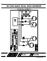
Страница 17: ...RIGHT ACHINE W 1904 QUAD DUAL SIDE GRINDER Revised 10 30 98 16 ELECTRICAL SCHEMATIC ...

Страница 18: ...RIGHT ACHINE W 1904 QUAD DUAL SIDE GRINDER Revised 10 30 98 17 ELECTRICAL SCHEMATIC ...

Страница 19: ...RIGHT ACHINE W 1904 QUAD DUAL SIDE GRINDER Revised 10 30 98 18 ELECTRICAL SCHEMATIC ...

Страница 20: ...RIGHT ACHINE W 1904 QUAD DUAL SIDE GRINDER Revised 10 30 98 19 NOTE USE SIDE DIAL INDICATOR WITH CLAMP JAWS CLOSED THIS WILL INSURE PROPER MEASUREMENT ...

Страница 21: ...ollowing page LEFT END OF BASE OUTSIDE QTY PART NUMBER DESCRIPTION 2 F 25 NYLOCK NUTS 2 F 70 BELLEVILLE WASHER 2 F 106 1 4 20 SOCKET HEAD CAP SCREW 6 F 107 1 4 20 SOCKET HEAD CAP SCREW 2 F 269 1 2 13 BOLT 6 F 647 ELBOW FITTING 1 W 240 HANDLE 1 W 253 COMPRESSION SPRING 2 W 284 GROUND WASHER 2 W 733 BEARING 1 W 2170 1 ROLLER BRACKET LEFT 1 W 2171 ROLLER TIE PLATE 1 W 2171 1 ROLLER TIE PLATE 2 W 2172...

Страница 22: ...RIGHT ACHINE W 1904 QUAD DUAL SIDE GRINDER Revised 10 30 98 21 LEFT END OF BASE OUTSIDE ...

Страница 23: ...ASHER 2 F 106 1 4 20 SOCKET HEAD CAP SCREW 6 F 107 1 4 20 SOCKET HEAD CAP SCREW 2 F 269 1 2 13 BOLT 6 F 647 ELBOW FITTING 1 W 240 HANDLE 1 W 253 COMPRESSION SPRING 2 W 284 GROUND WASHER 2 W 733 BEARING 1 W 2170 ROLLER BRACKET RIGHT 1 W 2171 ROLLER TIE PLATE 1 W 2171 1 ROLLER TIE PLATE 2 W 2172 ROLLER ARM 2 W 2175 CLAMP CYLINDER MOUNT 3 W 2236 AIR CYLINDER ...

Страница 24: ...RIGHT ACHINE W 1904 QUAD DUAL SIDE GRINDER Revised 10 30 98 23 RIGHT END OF BASE OUTSIDE ...

Страница 25: ...ON 2 F 18 5 16 18 JAM NUT 4 F 107 1 4 20 CAP SCREW 6 F 111 5 16 18 CAP SCREW 4 F 131 8mm CAP SCREW 8 F 133 8mm CAP SCREW 2 F 386 5 16 18 SET SCREW 4 F 647 ELBOW FITTING 1 W 1406 TRACK TRUCK ASSEMBLY 1 W 2051 9 MOUNT PLATE 1 W 2173 INDEX BEARING MOUNT PLATE 2 W 2175 CLAMP CYLINDER MOUNT 2 W 2236 AIR CYLINDER ...

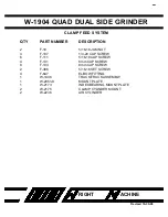
Страница 26: ...RIGHT ACHINE W 1904 QUAD DUAL SIDE GRINDER Revised 10 30 98 25 FRONT VIEW OF CLAMP FEED SYSTEM ...

Страница 27: ...PART NUMBER DESCRIPTION 2 F 54 6 WASHER 3 F 56 10 WASHER 3 F 59 FENDER WASHER 7 F 70 BELLEVILLE WASHER 7 F 279 3 8 16 HEX HEAD BOLT 3 F 333 10 24 SET SCREW 2 F 335 6 32 CAP SCREW 1 W 1051 C CYLINDER JAM NUT 1 W 1051 1 DAMPENER CYLINDER 1 W 2131 FRAME 1 W 2200 RADIAL SCALE 1 W 2207 PROXIMITY SWITCH ...

Страница 28: ...RIGHT ACHINE W 1904 QUAD DUAL SIDE GRINDER Revised 10 30 98 27 FRAME MOUNT FOR GRINDING HEAD ...

Страница 29: ...0 CAP SCREW 1 F 376 1 4 20 SET SCREW 1 F 392 1 2 20 SET SCREW 2 F 394 5 16 18 SET SCREW 1 W 357 2 ZERK FITTING 1 W 992 THRUST BEARING 1 W 1032 2 DEPTH FEED KNOB 1 W 1033 MARK RING 1 W 1055 LEAD SCREW 1 W 2124 DEPTH STOP SIDE 1 W 2153 A1 1 2 13 BOLT 1 W 2154 A BEARING BOSS 1 W 2154 B BEARING BOSS 1 W 2157 BEARING BOSS SPACER 1 W 2158 PIVOT SHAFT 1 W 2164 LEAD SCREW NUT 2 W 2217 FLAT GROUND WASHER 1...

Страница 30: ...RIGHT ACHINE W 1904 QUAD DUAL SIDE GRINDER Revised 10 30 98 29 INNER GRINDING HEAD ASSEMBLY ...

Страница 31: ...8 SET SCREW 1 W 71 WASHER 1 W 357 2 ZERK FITTING 1 W 733 BEARING 1 W 992 THRUST BEARING 1 W 1032 2 DEPTH FEED KNOB 1 W 1033 MARK RING 1 W 1055 LEAD SCREW 1 W 2124 DEPTH STOP SIDE 1 W 2153 B OUTSIDE MOTOR ARM WELDMENT 1 W 2154 A BEARING BOSS 1 W 2154 B BEARING BOSS 1 W 2157 BEARING BOSS SPACER 1 W 2158 PIVOT SHAFT 1 W 2164 LEAD SCREW NUT 1 W 2187 ECCENTRIC 1 W 2217 FLAT GROUND WASHER 1 W 2218 THRUS...

Страница 32: ...RIGHT ACHINE W 1904 QUAD DUAL SIDE GRINDER Revised 10 30 98 31 OUTER GRINDING HEAD ASSEMBLY ...

Страница 33: ...AD ARM ASSEMBLY QTY PART NUMBER DESCRIPTION 8 F 56 10 WASHER 8 F 59 FENDER WASHER 6 F 70 BELLEVILLE WASHER 4 F 104 1 4 20 CAP SCREW 6 F 279 3 8 16 HEX HEAD BOLT 1 F 284 5 8 UNF HEX HEAD BOLT 8 F 333 10 24 CAP SCREW 1 F 436 1 4 X 1 DOWEL PIN 2 W 2132 2 CYLINDER PIVOT MOUNT ...

Страница 34: ...RIGHT ACHINE W 1904 QUAD DUAL SIDE GRINDER Revised 10 30 98 33 GRIND HEAD ARM ASSEMBLY ...

Страница 35: ...F 61 12 WASHER 2 F 104 1 4 20 CAP SCREW 2 F 122 3 8 16 CAP SCREW 1 F 391 1 4 20 SET SCREW 1 F 608 FITTING 1 F 612 1 SHUT OFF VALVE 1 F 620 ELBOW FITTING 2 W 436 THRUST BEARING 4 W 667 FLAT GROUND WASHER 1 W 1294 C 1 8 N P T CONNECTOR 2 W 1411 O RING 1 W 2184 1 INDEX FINGER ARM 1 W 2185 FINGER PIVOT 1 W 2186 1 INDEX FEED FINGER 1 W 2188 BEARING COVER 1 W 2188 1 BEARING COVER ...

Страница 36: ...RIGHT ACHINE W 1904 QUAD DUAL SIDE GRINDER Revised 10 30 98 35 FEED FINGER ASSEMBLY ...

Страница 37: ...CRIPTION 5 F 110 5 16 18 CAP SCREW 2 F 392 1 2 20 SET SCREW 4 F 333 1 10 24 ROUND HEAD SCREW 2 F 407 3 16 ROLL PIN 1 W 2178 1 OUTER CLAMP JAW 1 W 2179 OUTER CLAMP STIFFENER 2 W 2181 CLAMP CYLINDER ATTACHMENT BRACKET 2 W 2182 CLAMP JAW ATTACHMENT BRACKET 4 W 2183 HOSE HOLDER 2 W 2236 CLAMP CYLINDER ...

Страница 38: ...RIGHT ACHINE W 1904 QUAD DUAL SIDE GRINDER Revised 10 30 98 37 TOP VIEW OF CLAMP ASSEMBLY ...

Страница 39: ... 13 BOLT MODIFIED 2 F 313 1 4 20 FLAT HEAD SCREW 2 F 333 10 24 SCREW 2 F 378 1 4 20 SET SCREW 2 F 380 1 4 20 SET SCREW 1 F 434 1 4 DIA PIN 2 F 671 AIR FITTING 1 W 284 WASHER 1 W 508 TOMSON SHAFT 1 W 1000 1 NUT 1 W 1402 HEAVY DUTY INDEX AIR CYLINDER 1 W 1404 PROXIMITY SWITCH 1 W 1469 ENDINE CYLINDER 1 W 2032 CLEVIS 1 W 2033 CYLINDER LINK 1 W 2034 MOUNT BRACKET B 1 W 2035 MOUNT BRACKET A 1 W 2036 MO...

Страница 40: ...RIGHT ACHINE W 1904 QUAD DUAL SIDE GRINDER Revised 10 30 98 39 INDEX ASSEMBLY TOP VIEW FRONT VIEW ...

Страница 41: ...N 1 F 23 3 8 16 NYLOCK NUT 1 F 11 10 24 NUT 2 F 60 5 16 WASHER 1 F 122 3 8 16 BOLT 1 F 137 10 24 BOLT 2 F 671 HOSE FITTING 1 W 1000 1 CYLINDER NUT 1 W 1403 ROD END 1 W 1404 PROXIMITY SWITCH 1 W 2132 2 CYLINDER PIVOT MOUNT 1 W 2209 1 AIR CYLINDER 1 W 2228 HEAD RETURN SPRING 1 W 2450 SPACER 1 W 2451 CYLINDER TARGET ...

Страница 42: ...RIGHT ACHINE W 1904 QUAD DUAL SIDE GRINDER Revised 10 30 98 41 INDEX CYLINDER ASSEMBLY ...

Страница 43: ...GRINDER Revised 10 30 98 42 FEED LIMIT ASSEMBLY QTY PART NUMBER DESCRIPTION 1 F 140 10 24 CAP SCREW 1 F 378 1 4 20 SET SCREW 2 F 382 SPRING 1 F 410 ROLL PIN 1 W 2124 DEPTH STOP 1 W 2452 TARGET FRAME 1 W 2453 DEPTH NUT 1 W 2454 SET COLLAR ...

Страница 44: ...RIGHT ACHINE W 1904 QUAD DUAL SIDE GRINDER Revised 10 30 98 43 FEED LIMIT ASSEMBLY ...

Страница 45: ... 1 1 2 SCREW 1 W 298 14 14 AMP FUSE 1 W 2202 Q SHEET METAL PANEL 7 W 737 1 RELAY W LIGHT 7 W 738 RELAY BASE 13 W 704 6 LARGE DIN RAIL 1 W 739 TIME DELAY 1 W 740 TIME DELAY BASE 1 W 1152 MACHINE TOOL TRANSFORMER 52 W 1446 1 X 2 SLA TRACK 2 W 1420 2 NO AUX CONTACT BLOCK 2 W 1420 A N MOTOR STARTER 2 W 1421 4 N OVERLOAD 3 W 1463 FEMALE TERMINAL BLOCKS 3 W 1464 MALE TERMINAL BLOCK 8 5 W 1465 MINI DIN R...

Страница 46: ...RIGHT ACHINE W 1904 QUAD DUAL SIDE GRINDER Revised 10 30 98 45 SUB PANEL ASSEMBLY ...

Страница 47: ...HER 4 F 110 5 16 18 CAP SCREW 16 F 116 3 8 16 CAP SCREW 1 F 268 1 2 13 HEX BOLT 1 F 287 1 2 13 HEX BOLT 8 F 64 10mm WASHER 2 F 438 WOODRUF KEY 4 W 284 GROUND WASHER 4 W 330 5 8 BORE PILLOW BLOCK 4 W 1318 1 2 13 STUD 1 W 2089 SAW LIFT FRAME 2 W 2090 SAW LIFT NUT GUIDE 2 W 2091 LEAD SCREW 1 W 2093 CHAIN TENSION ARM 1 W 2211 DRIVE SPROCKET 4 W 2212 SPROCKET 1 W 2213 IDELER SPROCKET 1 W 2224 SAW LIFT ...

Страница 48: ...RIGHT ACHINE W 1904 QUAD DUAL SIDE GRINDER Revised 10 30 98 47 SAW LIFT ASSEMBLY ...

Страница 49: ...8 48 SAW CARRIER ASSEMBLY QTY PART NUMBER DESCRIPTION 2 F 170 5 8 X 1 1 4 SHOULDER BOLT 2 F 268 1 2 13 HEX HEAD BOLT 8 F 316 1 2 13 FLAT HEAD BOLT 2 W 2095 SAW ATTACH ROCKER 2 W 2096 ROCKER BUSHING 4 W 2097 FRONT SAW GUIDE 4 W 2231 1 8 X 1 4 X 2 CARBIDE BLANK ...

Страница 50: ...RIGHT ACHINE W 1904 QUAD DUAL SIDE GRINDER Revised 10 30 98 49 SAW CARRIER ASSEMBLY ...

Страница 51: ...ANEL 8 9 CONVERSION CHART 16 COOLANT 7 COOLANT CONCENTRATE 6 CRATE SIZE 5 E EAR PROTECTION 3 ELECTRICALSCHEMATIC 17 18 19 EYE PROTECTION 3 G GENERAL SAFETY RULES 3 GRINDING WHEELS 7 L LIMITED WARRANTY 2 LOAD METER 9 LOADING SAW 12 13 M MACHINE CONTROLS 11 N NARROW BAND SAW CARRIER 6 O OPEN POSITION 9 OPTIONAL SAW SIZE 5 OPTIONAL VOLTAGE 5 OPTIONS 6 ...

Страница 52: ...AL ANGLE 14 15 16 RUN POSITION 9 RUST DAMAGE 7 S SAFETY RULES 3 SAW UP SAW DOWN 9 SETTING INDEX PITCH 11 SHIPPING WEIGHT 5 SLIVER TOOTH 6 SPECIFICATIONS 5 SPINDLE MOTORS 5 STANDARD SAW SIZE 5 STANDARD VOLTAGE 5 STANDS 6 T TANGENTALANGLE 14 15 16 TOOTH COUNTER 9 TOOTH GEOMETRY 14 TOTALIZER COUNTER 6 ...

Отзывы: