Rev 1.0/2-17
4
#35204
OPERATION
A
BOUT THE
T
ILT
L
OCK
Although the tilt linkage normally holds a balanced load in position, the Tilt Lock can be used to
prevent tilt motion due to wind loads or other unexpected forces. The Tilt Lock should only be
needed if the operator cannot maintain control of the load using the control handle or other
appropriate means (such as when using the lifter to install glass in multi-story buildings). The
Tilt Lock is a secondary safety device and does not eliminate the need to load the lifter correctly
(see OPERATION: T
O
A
PPLY THE
P
ADS TO A
L
OAD
in MRTA8 lifter's instruction manual).
Caution: Failure to load lifter correctly may damage Tilt Lock or other lifter
components.
The Tilt Lock can be set to engage automatically when the pad frame reaches the vertical or
horizontal position, or it can be deactivated, depending on the application.
T
O
U
SE THE
T
ILT
L
OCK
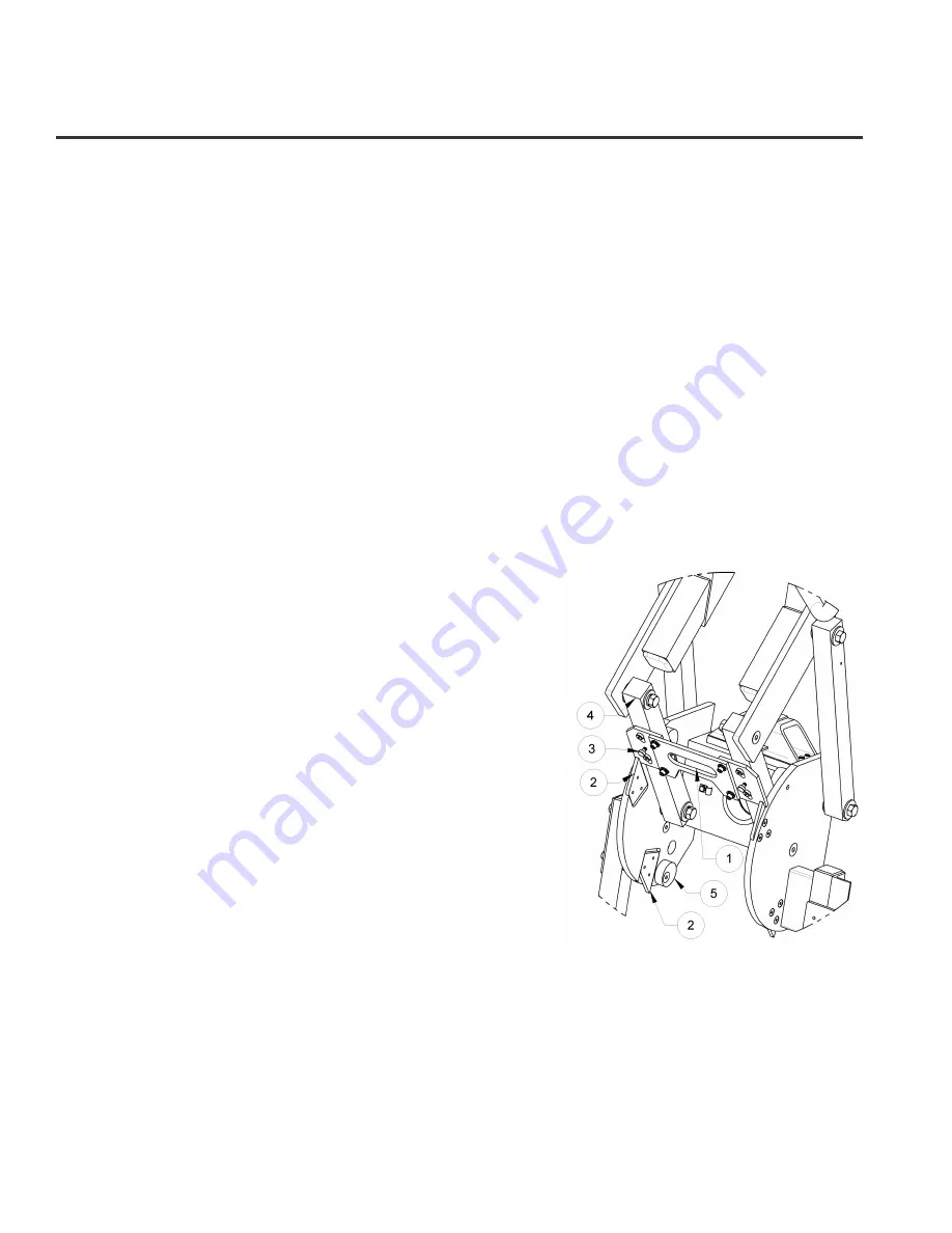
To allow automatic locking, make sure the lock handle/catch plate
assembly (#1) is set to slide up and lock behind the lock ramp plates
(#2) when the pad frame moves to either the vertical or horizontal
position. If not, pull outward on the round knobs of the two
spring plungers (#3) and turn them 90° to release the
handle/catch plate assembly. Make sure that the catch plates
slide freely along the bars of the tilt linkage (#4) before you
attempt to tilt the pad frame. If the catch plates do not lock
behind the ramp plates or if the pad frame exhibits excessive
play in either the vertical or the horizontal orientation, the
stop cams (#5) for the tilt linkage may require adjustment
(see INSTALLATION step 7). Once the Tilt Lock is set to the
automatic mode, simply pull on the lock handle to disengage
the lock.
T
O
D
EACTIVATE THE
T
ILT
L
OCK
Make sure the lock handle/catch plate assembly (#1) is
secured so that it
cannot lock behind the ramp plates (#2). If
otherwise, turn the round knobs of the spring plungers (#3)
90° and then slide the lock handle/catch plate assembly
upward until the spring plungers engage. Make sure that the
catch plates do not slide along the bars of the tilt linkage (#4).
1) LOCK HANDLE/CATCH PLATES
2) LOCK RAMP PLATE
3) SPRING PLUNGER
4) TILT LINKAGE
5) TILT STOP CAM


