background image

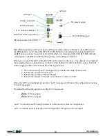
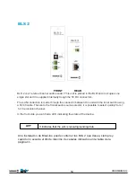
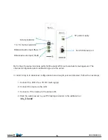
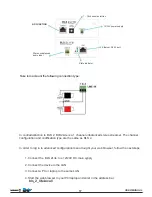
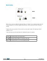
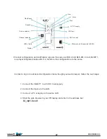
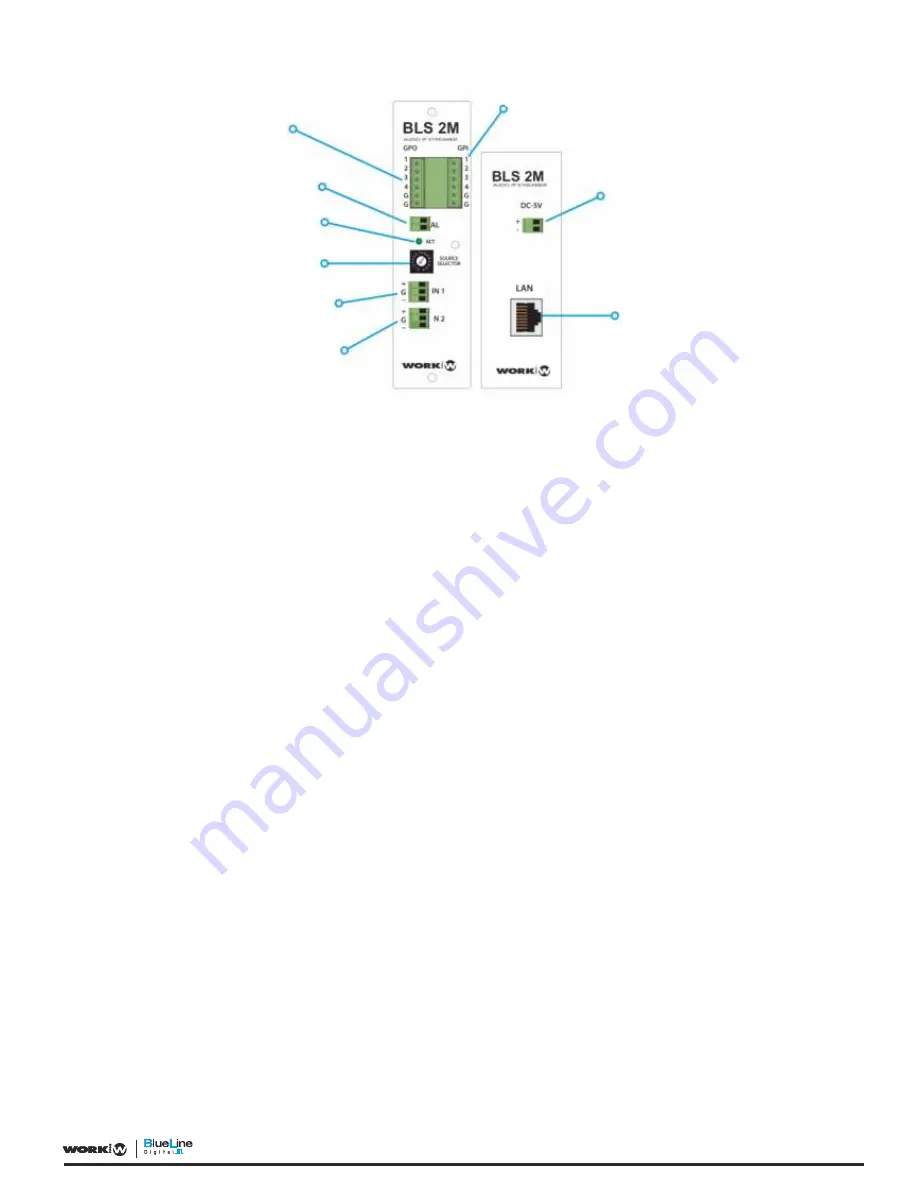
GPI port

5V power supply

RJ 45 Ethernet port

Balanced audio input (IN-B)

Balanced audio input (IN-A)

1 to 16 channel selection

Activity indicator

Alarm connection

GPO port

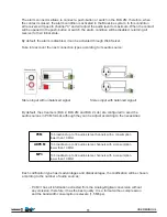
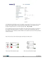
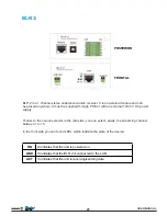
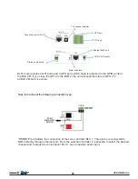
BLS 2M incorporates 4 GPI ports and 4 GPO ports which state is reflected in the GPIO ports of 
the BLR devices. If you clese the GPI 2 in the BLS 2M, the unit will send the state al GPO 2 in 
all BLR and vice versa. Take into account that when you close one GPI in the BLS 2 M, its state
 will appears in all BLR with GPIO, although they are in different channels.

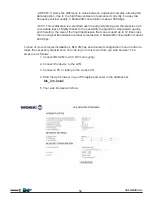
When you act over the GPI 1 in the BLS 2M, all the device in the zone 2 (by default, we considerer
them paging zone or receiver zone) to “listen” in the channel “0" with maximum volume. This will
act the paging function which made the following functions:

1. The unit sends a "push*" message which includes the state of the device.
2. It sends the command "source=0"
3. It sends the command "Mode=Single"
4. It sends the Master, Channel1 and channel 2 volume to 0 dB

When the GPI 1 is disactivated, it sends a "pop*" message which loads the configuration previous
to "push" message.

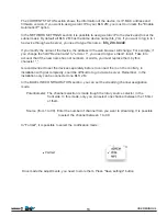
By default the BlueLine system is configured in two zones:


  Zone 1

: For senders


 Zone 2

: For receivers

push*: Command usedf to read the state of a device and to store its configuration

pop*: Command used to load the stored configuration through a push command

USER MANUAL

10

Содержание BlueLine Digital

Страница 1: ...User manual English version Rev 141101 ...

Страница 2: ...14 BLS 2Lite 17 BLMP 1 20 BLR 2 23 BLR 2Lite 28 BLR 2A 31 BLC1 34 OSC Protocol 36 OSC for working with properties 38 Overview of the BlueLine protocol 40 packet types in BluLine protocol 42 UDP IP protocols configuration 43 BlieLine protocol packets 44 Basic notions about LAN networks 46 I 48 Basic notions about IP protocol ...

Страница 3: ...unction if is exposed to high levels of moisture The internal oxidation can cause damage Do not hit it This product may malfunction it it is subjected to strong shock and vibration Keep away from strong magnetic fields Do not use or place the unit near equipments that generate strong fields of electromagnetic radiation or magnetic fields Heavy loads of these fields as radio transmitters can interf...

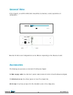
Страница 4: ...ons can be different depending on the BlueLine model The following accessories are included in the BlueLine Digital 1x Main supply cable Use this main power cable included in order to feed the BlueLine Digital 7x Individual covers Use these pieces to cover the empty slots 22x Screws Use these screws to fix the individial covers in the empty slots USER MANUAL 4 ...

Страница 5: ...lay system the intallers does not need any type of technical knowledge about network The central system is IP therefore it is possible to monitorize the netweok in order to check if any device in the systen does not work properly It anything happens an alarm message will be sent automatically to the users in order to check the system BlueLine digital is also compatible with other public address sy...

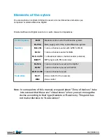
Страница 6: ...LS 2 1 stereo channel sender for BLM BLS 2 LITE 1 unbalanced stereo channel sender external BLMP 1 MP3 player with FM radio tuner Receivers BLR 2A 1 stereo channel receiver with amplifier BLR 2 1 stereo channel receiver with GPIO BLR 2 LITE 1 stereo channel receiver Controllers BLC 1 Zone control for the receivers WNC Zone control Note In some points of this manual we speak about Zone of devices t...

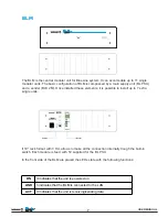
Страница 7: ...ingle modular units The basic configuration of BLM is compossed by a main supply unit BL PSU and a sender BLS 2M Once installed these elements it is possible to install up to 7 extra single units It 19 rack format with 3 HU allows to make all the connection internally trough the built in switch Each module is feed with 5V supplied for the BL PSU In the front side of the BLM are placed the LEDs sta...

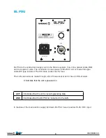
Страница 8: ...ugh a cable IEC type included The IEC base socket has 1A fuse The LAN connection is made through a RJ 45 base socket and it has 2 LEDs of state It indicates that the unit is powered on It indicates that the BL PSU is connected to the LAN It indicates that the unit is receiving sending data In thecase of the main electric supply fall down BL PSU has an auxiliar 18 36 V DC input USER MANUAL 8 ...

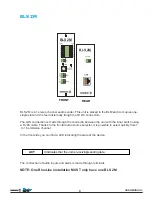
Страница 9: ...ly trough the 5V DC connectors The LAN connection is made through the connectin between the unit with the inner switch using a RJ 45 cable Thanks to the frontal audio source selector it is possible to select quickly from 1 to 16 emmision channel In the front side you can find a LED indicating the state of the device The connection of audio inputs and alarm is made through terminals NOTE One BlueLi...

Страница 10: ...the device in the zone 2 by default we considerer them paging zone or receiver zone to listen in the channel 0 with maximum volume This will act the paging function which made the following functions 1 The unit sends a push message which includes the state of the device 2 It sends the command source 0 3 It sends the command Mode Single 4 It sends the Master Channel1 and channel 2 volume to 0 dB Wh...

Страница 11: ... Stereo input with balanced signall By default the streamers BLS 2 BLS 2M and BLS 2 Lite are configured to send the audio sources in PCM format although they can be adjust according to the necessities To broadcast up to 16 audio stereo channels with a consumption lower than 10 Mbit To broadcast up to 32 audio stereo channels with a consumption lower than 10 Mbit To broadcast up to 64 audio stereo ...

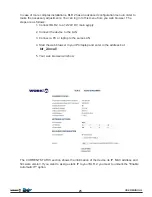
Страница 12: ...refore the size of the final transmission that can occuped up to 12 times less than an original transmission without compression It bandwidth consumption is about 220 Kbps In case of more complex installations BLS 2M has an advanced configuration menu in order to make the necessary adjustments You can log in to this menu from you web browser The steps are as follows 1 Connect BLS 2M to a 5V DC mai...

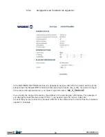
Страница 13: ... that if the new name has not numbers or words you must replace them by this character _ Is recommended to set the devices separately before to connect them on the contrary in installation with grat complexity could be difficult to log in via web server Remember in the installation only can be connected one BLS 2 M In the BLUELINE CONFIGURATION section you can set the streaming channel assignation...

Страница 14: ...LM and it occupies one single slot and it is supplied internally trough the 5V DC connectors The LAN connection is made through the connectin between the unit with the inner switch using a RJ 45 cable Thanks to the frontal audio source selector it is possible to select quickly from 1 to 16 emmision channel In the front side you can find a LED indicating the state of the device It indicates that th...

Страница 15: ...l If you modify the name of the device the address in the web browser will change For example if you change the field Device name to emisor 8 you need to type emisor8 local Take into account that you can connect any number of BLS 2 in the network but not more than the maximum number of channels Take into account the next connection types according to its audio source Stereo input with unbalanced s...

Страница 16: ...and alarm management The channel configuration and codification type are the same In order to log in to advanced configuration menu trought your web browser follow the next steps 1 Connect the BLS 2 to a 5V DC main sypply 2 Connect the device to the LAN 3 Connect a PC or laptop to the same LAN 4 Start the web browser in your PC laptop and enter in the address bar bls_2 local USER MANUAL 16 ...

Страница 17: ...l streamer The channel configuration and codification type are the same as BLS 2 In order to log in to advanced configuration menu trought your web browser follow the next steps unbalanced stereo 1 Connect the BLS 2Lite to a 12 24V DC main sypply 2 Connect the device to the LAN 3 Connect a PC or laptop to the same LAN 4 Start the web browser in your PC laptop and enter in the address bar bls_2_lit...

Страница 18: ...ernal 12 24 V DC power supply Thanks to the source selector in the rear side you can select easily the streaming channel between 1 to 16 In the front side you can found LEDs which indicate the state of the device ON It indicates that the unit is powered on LINK Ii indicates that the BLM is connected to the LAN ACT It indicates that the unit is receiving sending data USER MANUAL 18 ...

Страница 19: ..._2_lite if you want to log in to the device through web server you need to type this name bls_2_lite local If you modify the name of the device the address in the web browser will change For example if you change the field Device name to PC1 you need to type PC1 local Take into account that you can connect any number of BLS 2 in the network but not more than the maximum number of channels USER MAN...

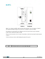
Страница 20: ... into the BLM The adio files can be played from an USB stick or SD card both of them must be formatted in FAT32 with a maximum storage of 32 GB Thanks to source selector in the front side it is possible to select the streaming channels between 1 and 16 In the front side you can fin a LED inditating the state of the device It indicates that the unit is receiving sending data USER MANUAL 20 ...

Страница 21: ...in to the device through web server you need to type this name bl_mp1 local If you modify the name of the device the address in the web browser will change For example if you change the field Device name to Player1 you need to type Player1 local Take into account that you can connect any number of BLMP 1 in the network but not more than the maximum number of channels USER MANUAL 21 ...

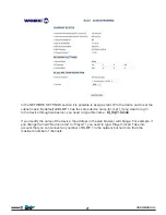
Страница 22: ...2 and BLS 2M In fact BLMP 1 is a player integrated inside a BLS 2 herefore the configuration are the same In order to log in to advanced configuration menu trought your web browser follow the next steps 1 Connect the BLMP 1 to a 5V DC main sypply 2 Connect the device to the LAN 3 Connect a PC or laptop to the same LAN 4 Start the web browser in your PC laptop and enter in the address bar bl_mp1 lo...

Страница 23: ...l 12 24 V DC power supply Thanks to the source selector in the rear side you can select easily the streaming channel between 1 to 16 In the front side you can found LEDs which indicate the state of the device ON It indicates that the unit is powered on LINK It indicates that the BLR 2 is connected to the LAN ACT It indicates that the unit is receiving sending data USER MANUAL 23 ...

Страница 24: ... 2M and vice versa Connection por for BLC 1 Stereo audio output State indicators 12 24V DC supply Ethernet RJ45 port GPI port GPO port 1 16 channel selector REMOTE port allows the connection of the zone controller BLC 1 This device is connected to BLR 2 directly through ethernet port From the external controller it is possible to select the desired channel and to adjust de volume level BLC 1 has a...

Страница 25: ...2 24V DC main sypply 2 Connect the device to the LAN 3 Connect a PC or laptop to the same LAN 4 Start the web browser in your PC laptop and enter in the address bar blr_2 local 5 Your web browser will show The CURRENT STATUS section shows the information of the device its IP MAC address and firmware version If you want to assig a static IP to your BLR 2 you must to unmark the Enable Automatic IP o...

Страница 26: ...stallation with grat complexity could be difficult to log in via web server Remember in the installation can be connected whatever number of BLR 2 In the BLUELINE CONFIGURATION section you can set the streaming channel assignation mode Potentiometer The channel selection is made trough the rotary source selector in the front side In this mode only you can select one channel between the 16 first of...

Страница 27: ...ead of two equal signals by default can be configured one balanced output through webserver Once selected Single mode The output mode change through webserver Take into account that in this mode the sources operate channel to channel In Dual and Mono modes the sources operate sender to sender The output operation is the same as single mode 2 unbalanced outputs by default or 1 balanced output Mono ...

Страница 28: ...o the source selector in the rear side you can select easily the streaming channel between 1 to 16 In the front side you can found LEDs which indicate the state of the device ON It indicates that the unit is powered on LINK It indicates that the BLR 2 Lite is connected to the LAN ACT It indicates that the unit is receiving sending data One BlueLine installation can be connected whatever number of ...

Страница 29: ...ame LAN 4 Start the web browser in your PC laptop and enter in the address bar blr_2_lite local 5 Your web browser will show If you modify the name of the device the address in the web browser will change For example if you change the field Device name to receiver 2 you need to type receiver2 local USER MANUAL 30 ...

Страница 30: ...troller it is possible to select the desired channel and to adjust de volume level BLC 1 has an auxiliar audio input For further information go to page xxxxxxxxxxxxxxxx BLR 2Lite includes the same function of BLR 2 except the GPIO ports management Channel configuration and operating modes are the same as BLR 2 In case of more complex installations BLR 2 has an advanced configuration menu in order ...

Страница 31: ...th an external 12 24V DC power supply Thanks to the source selector in the rear side you can select easily the streaming channel between 1 to 16 In the front side you can found LEDs which indicate the state of the device ON It indicates that the unit is powered on LINK It indicates that the BLR 2A is connected to the LAN ACT It indicates that the unit is receiving sending data USER MANUAL 31 ...

Страница 32: ...ontroller BLC 1 This device is connected to BLR 2A directly through ethernet port From the external controller it is possible to select the desired channel and to adjust de volume level BLC 1 has an auxiliar audio input BLR 2A includes the same function of BLR 2Lite but also it includes 2 amplified outputs Channel configuration and operating modes are the same as BLR 2Lite Depending on how feeds t...

Страница 33: ...o make the necessary adjustments You can log in to this menu from you web browser The steps are as follows 1 Connect BLR 2A to a 12 24V DC main sypply 2 Connect the device to the LAN 3 Connect a PC or laptop to the same LAN 4 Start the web browser in your PC laptop and enter in the address bar blr_2_a local 5 Your web browser will show USER MANUAL 33 ...

Страница 34: ... be carried CAT5 cable between REMOTE ports of both devices Take into account that the REMOTE port in BLS 2Lite has no fuction and therefore the BLC 1 can not be connected here BLC 1 is mounted in a surface box onece the device is installed it as a dimmensions of 85 x 85 x 40 mm The auxiliar input connection is made through stereo minijack connector 3 5 mm USER MANUAL 34 ...

Страница 35: ...single message High resolution time marks Packed messages for those events that must occur simultaneously Interrogation system to dinamically find the capabilities of a OSC server and get documentation It can be transported by various protocols but UDP is normally used The format of the OSC messages is the next OSC Address Pattern OSC Type Tag String OSC Arguments OSC Address Pattern It is a strin...

Страница 36: ...Auxiliar audio input Channel selector Audio level adjustment Selection channel indicator Audio level indicator USER MANUAL 36 ...

Страница 37: ...OTE All data are aligned to 4 bytes therefore the data do not occupy a multiple of four must add enough bytes with value 0x00 up to a multiple size of four NOTE 2 All strings end in 0x00 null OSC Address Pattern y OSC Type Tag String are strings therefor will always have to end in 0x00 y aligned to four bytes This byte to 0 also account for computing the size of the string For example hola 23 has ...

Страница 38: ...perty Incremental writing bl ZONE PROPERTY inc with only one parameter of type the property is with the increment value we want to assign Reading bl ZONE PROPERTY get with no parameter The device will respond with a shortened set message continue reading Due to the variety of messages can be shortened to Writing bl ZONE PROPERTY with only one parameter This is the message short writing exactly as ...

Страница 39: ...ifications are as follows OSC Message multicast to IP 239 192 0 98 port 9001 This message path is formed as follows DEVICE_NAME ENTIRE_PATH OSC Message unicast to IP and ports that are registered as listeners To this must be registered with the appropriate command later is indicated The path of this message is the same as the property USER MANUAL 39 ...

Страница 40: ... the sender of the packets choose one or the other depending on the needs Common packets are always Unicast The BlueLine Digital system allows grouping devices into zones A zone is a set of devices that have the same logical behavior For example security zone room zone Zones allow us to ship orders to multiple devices at once By default all devices are assigned to a particular zone ZONE 0 broadcas...

Страница 41: ...e following structure bl ZONE MESSAGE In the packet address the zone to which the message is intended is encoded For a better understanding of the areas of the system in to the master device can assign a name to each of existing areas USER MANUAL 41 ...

Страница 42: ...one The send address of the packet is the multicast address as send address provided data The field zone is set in the zone to control NOTE As the packet is multicast all devices receive the information Those devices whose area does not correspond to the area specified in the packet is discarded Broadcast The packet is executed by all devices in the system The send address of the packet is the mul...

Страница 43: ...ion of control messages 239 192 0 101 SOURCE For the transmission of audio packets Each SOURCE uses a different IP address Starts with SOURCE 0 Device IP You can also use the IP Unicast assigned to the device to transmit control messages The UDP protocol is used in the following ports 3125 for the reception of audio packets 3126 for the reception of control packets USER MANUAL 44 ...

Страница 44: ...C messages All messages have as the first parameter in the name the zone wich the message is intended Named parameters are indicated by a number in square brackets For Example bl 1 source indicates a parameter after bl and before source and that the text 1 should be replaced by an appropriate value in this case would be the number of zone for example bl 0 source BlueLine command devices OSC Addres...

Страница 45: ... pair cable is 100 m while for optical fiber the maximum length varies between 10 km to 70 km depending on the cable type In general the networks should always have more capacity that necessary In order to prepare a network is a good idea to design a network that use about the 30 of the full capacity The majority of devices connected to the network like a laptop or webcam are equipped with an Ethe...

Страница 46: ...el Indicates the mute value of the selected channel in 2 Channel can be 1 for L y R máster 1 for L 2 for R bl 1 mode i Working Mode RECIVERS ONLY Sets the working mode of the device It may be 0 for Dual 1 for Single 2 for Mono bl 1 format i Audio Format SENDERS ONLY Sets the format of the audio data to be transmitted It may be 0 for ADPCM 1 for PCM 6 for MP3 Other values reserved and should not be...

Страница 47: ...efore we can identify easily the octets which belong to network and host id There are special adresses that must not be assigned to a host due to they have an own purpose Network addresses The network have their own address NetID with the network ID and HostID to 0 Example 150 214 0 0 Broadcast addresses They define the broadcast address to IP level It consists in the NetID with the network ID whe...

Страница 48: ...on or to add additional points Also the audio system security increases An audio system with PoE can supplies a server room that normally is protected with a UPS Uninterrupted power system therefore the audio system can operate even during power outage Due to its advantages it is advisable to use PoE in the majority of devices the powe of the switch or midspan with PoE should be enough to the conn...

Страница 49: ...ary The datagram is divided in two fields Head It has the information that the protocol needs to offer the service Data It has the message itself It must be delivered to destiny host The SubNet mask is a bits combination that is used to delimit the scope of a network Its function is to indicate to the devices which part of the IP address is the network number including t he subnet and which part c...

Страница 50: ...Silla Valencia Spain Tel 34 96 121 63 01 Fax 34 96 120 02 42 www workproaudio com support workproaudio com 2790 233 Carnaxide Telef 351 21 417 76 21 Fax 351 21 030 00 31 Web www sislite pt email geral sislite sislite pt R Sá de Figueiredo 6 C DISTRIBUIDOR EM PORTUGAL ...

Отзывы: