


PR
E-
IN
S
TA
LL
AT
IO
N
INSTALLATION & SERVICING INSTRUCTIONS FOR WORCESTER BOSCH
8-716-106-256a (08.05)
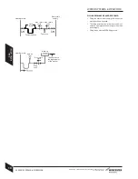
The table and illustration above is a guide only and does not in any way override the de-aerators
manufacturers instructions.
A
F
B C G
J
4m (
13ft
) max
.
B
A
D
B
C
B
E
K
3.5m (
11
.5ft
) max
.
K
150mm
L
L
B
A
M
B
F
C
G
J
K
3.5m (
11
.5ft
) max
.
E
E
D
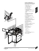
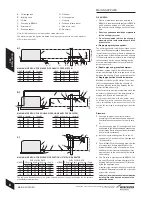
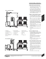
A - Oil storage tank
B - Isolating valve
C - Oil filter
D - Fire valve to BS5410
E - External wall
F - Fire valve sensor
G - Oil burner
H - Oil supply pipe
J - Oil pump
K - Full base (plastic tanks)
L - Non-return valve
M - De-aerator
HEAD 10mmØ
12mmØ
0.512
30
1.0
2569
1.537
91
2.0
49
100
HEAD 10mmØ
12mmØ
2.562
100
3.0
74
100
3.587
100
4.0
99
100
a)
b)
c)
Note: All dimensions are in metres unless stated otherwise.
The maximum pipe run figures are based on using copper pipe with an inside diameter
of 2mm less than the Ø.
MAXIMUM PIPE RUN FOR SINGLE PIPE GRAVITY FEED SYSTEM
HEAD 10mmØ
12mmØ
0
5
0
100
0.544
100
1.0
38
95
1.532
80
HEAD 10mmØ
12mmØ
2.0
26
66
2.520
5
0
3.0
14
37
3.58
22
MAXIMUM PIPE RUN FOR DOUBLE PIPE SUB-GRAVITY FEED SYSTEM
HEAD 2.5kg/h 5kg/h 10kg/h
10kg/h
8mmØ 8mmØ 8mmØ 10mmØ
0
100
55
26
100
0.5954523
100
1.0
80
40
20
90
1.570
3517
75
HEAD 2.5kg/h 5kg/h 10kg/h
10kg/h
8mmØ 8mmØ 8mmØ 10mmØ
2.0
60
30
14
65
2.5452511
5
0
3.0
3515 8
35
3.52510
5 20
MAXIMUM PIPE RUN FOR SINGLE PIPE SUCTION LIFT WITH DE-AERATOR
H
H
H
8
MAINS SUPPLIES
OIL SUPPLY:
Plastic or steel tanks should be installed to
BS5410. A steel tank should conform to BS799:
part 5 and have a slope of 1 in 24 away from
the outlet valve with a sludge cock at its lower
end.
Do not use galvanised steel tanks or pipework
for the oil supply system.
Do not use soldered joints on the oil supply
pipework as this could cause a hazard in the
event of a fire.
a) Single pipe gravity feed system:
The oil storage tank (A) must be positioned so that
the oil level does not exceed 4 metres above the
level of the burner oil pump (J) and in addition the
oil level must be at least 300mm above the oil pump
(J). Where the maximum oil level in the oil storage
tank exceeds 4 metres, a head breaking device
must be installed between the tank (A) and the
burner oil pump (J).
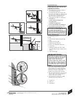
b) Double pipe sub-gravity feed system:
Maximum suction height 3.5 metres. Non-return
valves must be fitted to the inlet and return oil line
between the oil pump (J) and oil storage tank (A).
c) Single pipe suction lift with de-aerator
Maximum suction height 3.5 metres. The oil tank
(A) must be positioned below the oil pump (J).
Create an inlet and return loop between the de-
aerator (M) and oil pump (J).
A non-return valve must be incorporated within the
de-aerator or fitted to the oil line between the oil
storage tank (A) and the de-aerator (M).
A top feed oil tank fitted with a de-aerator using
an internal non-return valve should have any non-
return valve/s fitted in the base of the tank to the
suction line removed to assist purging air from the
oil line.
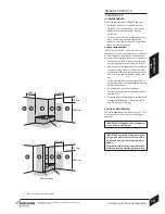
Pipework
Use copper pipe of the correct diameter
according to the information shown opposite.
Use flexible hoses to connect to the oil pump
(J).
Lay the oil supply pipe (H) as straight and level
as possible to avoid air pockets and unnecessary
friction losses. Route away from the boiler access
door or other hot surfaces.
Install a manual isolating valve (B) to the oil
supply pipe (H), as close to the oil storage tank
(A) as possible.
Fit an oil filter (C) to the oil supply pipe, near the
oil storage tank. If there is doubt about the
internal condition of the oil supply pipe, fit an
additional oil filter (recommended paper filter
element) close to the boiler, but not inside the
boiler casing.
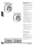
Fit a fire valve in accordance with BS5410. The
fire valve (D) should be fitted externally to the
building with the fire valve sensor (F) located
within the appliance case.
A capillary type valve provides a neat and simple
installation. Alternatively, a fusible link or electrical
system may be used.
Under no circumstances should a combination
isolating/fire valve be used as the sole fire
protection device.
F
C
G
J
FUEL FLOW RATE
FUEL FLOW RATE
MAINS SUPPLIES
30
0mm
min
.
B D
B C