


11.2.6 Telescopic Horizontal Flue Kit up to
750mm in Length
(i)
The standard flue can be telescopically adjusted to any
length between 425mm and 725mm.
It will only be necessary to cut the standard assembly if
L<425mm. Cut the flue turret assembly and the terminal
assembly by the same amount i.e L=350 - remove 75mm
from each assembly.
The minimum length L is 250mm with cutting.
General:
Cut the ducts as necessary, ensuring that the ducts are
square and free from burrs. Always check the dimensions before
cutting.
(i)
Fix the flue assembly together using the self-tapping
screws provided. Refer to Fig. 21, 22.
(ii)
Apply the plastic tape onto the duct in contact with the
wall (see Fig. 21, 22).
If an internal fitting kit is to be used refer now to Section 11.2.10
otherwise refer to Section 11.2.11.
11.2.7 Telescopic Horizontal flue Kit
Greater Than 750mm in Length
If bends are to be used refer also to Section 11.2.8.
(i)
By adding extension duct kits to the standard flue kit it is
not necessary to cut the extension ducts if
L is between
1175 - 1475mm
(1 extension)
1925 - 2225mm
(2 extension)
(ii)
However extension ducts need to be cut if
L is between
725 - 1175mm
(1 extension)
1475 - 1925mm (2 extension)
2225 - 2500mm (3 extension) 19/24 CBi
2225 - 2975mm
(3 extension) 14/19 and 19/24CBi
(iii)
To shorten the duct the first extension only should be cut.
To work out the length to be cut off:
(No. of extensions x 750) + 425 — L = length to be cut.
NOTE:
Extension duct measurements do not include the
socketed end. Unless specifically instructed the socketed
end must not be removed.
(iv)
Fix the flue assembly together using the self tapping
screws provided (see Fig. 20).
(v)
Apply the plastic tape onto the duct in contact with the
wall (see Fig. 20).
If an internal fitting kit is to be used refer now to Section 11.2.10
otherwise refer to Section 11.2.11.
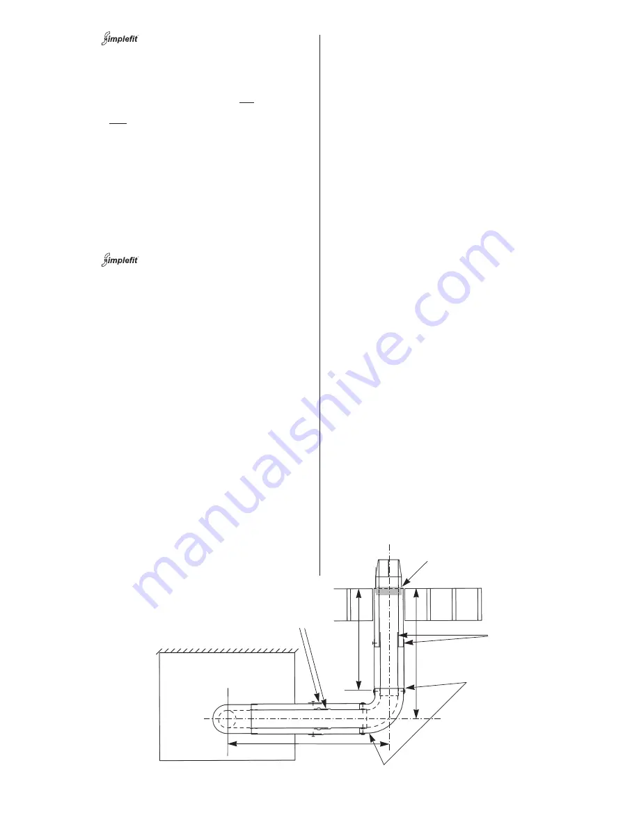
11.2.8 Flue Bends
90° and 45° directional bends are available. A maximum of two
45° or 90° bends may be used in addition to the first bend on
the flue turret.
A 90° bend is equivalent to 750mm of straight duct.
A 45° bend is equivalent to 0.375m of straight duct.
Measure the lengths X and Y. Refer to Fig.23.
The maximum value of X using the turret assembly only is
506mm. Reduce the ducts to the appropriate length e.g. X =
406mm, cut 100mm from the air duct and 120mm (to cover the
entry into the 45° or 90° elbow) from the flue duct. Refer to
Fig.24.
The final section, dimension Y, of the flue system must include a
section of plain duct assembly i.e . an extension assembly with
the sockets removed. Reduce the final section, including the
terminal assembly, by the appropriate amount i.e. Air duct Y -
81mm and the flue duct Y - 51mm. Refer to Fig.23.
If Y is smaller than425mm it will be necessary to cut the air and
flue ducts of the extension to a plain length of 100mm and
reduce the length of the terminal assembly e.g. Y=350mm -
remove 75mm from the terminal assembly.
If Y is between 425 and 725mm it is not necessary to cut the
terminal assembly or use a second extension duct as the length
can be set telescopically.
If Y is greater than 725mm then two extension duct assemblies
will be required, the first assembly being cut to length as plain
tubes.
If more than two extension ducts are needed in any section to
achieve the required length then the final section of the
assembly must not be less than 325mm without cutting the
terminal assembly.
NOTE: The flue duct of the final extension must be 30mm longer
than the air duct.
Each section must be connected to the previous section of the
flue bend by fixing the flue ducts together and then similarly
fixing the air ducts which engage the elbows.
Fix the flue assembly together using the self tapping screws
provided.
Apply the plastic tape onto the duct in contact with the wall (see
Fig. 23).
If an internal fitting kit is to be used refer now to Section 11.2.10
otherwise refer to Section 11.2.11.
20
Fig. 23. Flue bends.
Air Y
– 8
1mm
Flue Y
– 5
1mm
Y
X
Tape
Swaged ends
Plain ends
Note:
Connections to and from
bend should be plain ended and
the same length.
Содержание 14/19CBi
Страница 41: ...41 ...


