


Manual 37138C
ESDR 4T - Current Differential Protection Relay
The unit monitors six (6) measured currents via isolated inputs. The unit calculates internally the restraint current
(I
s
) and the differential current (I
d
) separately for each phase. The actual values of the calculated parameters (Dif-
ferential current I
d
und Restraint current I
S
) are shown on the display either as absolute values or as a percentage
of the generator rated current (selectable in locked input mode).
Theoretically the currents I
a
and I
b
are equal, both in fault-free operation and outside the protection zone (Figure
4-1-a).The difference is zero and the differential protection does not initiate. However, in practice current differ-
entials do occur (= spurious currents), even in fault-free operation. They result, for example, from summation or
phase angle errors in the CTs, which are influenced by deviating burden values. These spurious currents remain
small inside the operating range, but increase with increasing load and are especially high when one or more CTs
become saturated (e.g. in the case of an external short circuit). In order to prevent a tripping of the relay due to
spurious currents, the trigger threshold is not held statically constant but increases in relation to the restraint cur-
rent I
s
. Spurious currents need to be taken into account when adjusting the trip characteristic.
When a fault occurs inside the protection area (Figure 4-1-b), unequal currents flow in the CTs, which result in a
current differential. If this exceeds the differential protection threshold, the relay will trip.
G
I
I
I
L
G
I
I
I
L
a
a)
b
b)
a
b
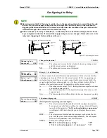
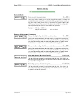
Schematic circuit diagrams (single phase version):
a) Fault outside the protection area
b)Fault inside the protection area
Figure 4-1: Protection principle
The circuit diagram above serves to explain the protection concept for in phase and equal currents. The differen-
tial current and restraint currents are determined arithmetically.
Measurement Inputs
≡≡≡≡≡≡≡≡≡≡≡≡≡≡≡≡≡≡≡≡≡≡≡≡≡
The unit records six current values for the current differential protection.
For differential current measurement, the unit forms the sum of two values (restraint current I
S
) and the deviation
(differential current I
d
). The actual value of the values determined (differential current I
d
and restraint current I
S
)
is shown as a percentage on the display with reference to the rated current.
© Woodward
Page 15/46