background image

-29-

W1752 Owner's Manual (Mfg. 1/07+)

SE

RV

IC

E

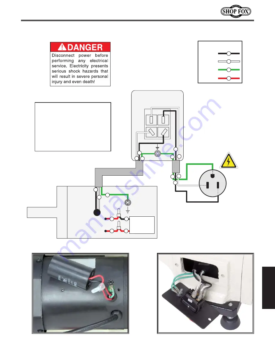
Wiring Diagram W1752

5-15 Plug

White

Neutral

Black

Hot

Green

Ground

PADDLE SWITCH

(viewed from behind)

110

VAC

MOTOR

Ground

Run

Capacitor

25MFD

250VAC

Bk

Rd

Rd

Rd

BLACK

WHITE

GREEN

RED

COLOR KEY

Bk

Wt

Gn

Rd

Bk

Bk

Bk

Bk

Wt

Wt

Wt

Wt

Gn

Gn

Gn

Gn

Figure 

27

. Motor connections. 

Figure 28

. Switch connections. 

NOTICE

This  motor  wiring  diagram  is 

current at the time of printing; 

however,  always  use  the  dia-

gram on the inside of the junc-

tion  box  cover  when  rewiring 

your motor!

Содержание SHOP FOX W1752 s

Страница 1: ...34 3482 Online Technical Support tech support shopfox biz COPYRIGHT JANUARY 2007 BY WOODSTOCK INTERNATIONAL INC REVISED AUGUST 2010 TR WARNING NO PORTION OF THIS MANUAL MAY BE REPRODUCED IN ANY SHAPE OR FORM WITHOUT THE WRITTEN APPROVAL OF WOODSTOCK INTERNATIONAL INC Printed in China 8952BL ...

Страница 2: ...f personal protective equipment The manufacturer will not be held liable for injury or property damage from negligence improper training machine modifications or misuse Some dust created by power sanding sawing grinding drilling and other construction activities contains chemicals known to the State of California to cause cancer birth defects or other reproductive harm Some examples of these chemi...

Страница 3: ... Placement 12 Cleaning Machine 12 Assembly 13 Test Run 14 OPERATIONS 15 General 15 Changing Speeds 16 Adjusting Tailstock 16 Adjusting Tool Rest 17 Installing Removing Spur Center 17 Installing Removing Live Center 18 Installing Removing Faceplate 19 Selecting Turning Tools 20 Spindle Turning 21 Faceplate Turning 23 Sanding Finishing 24 ACCESSORIES 25 Lathe Accessories 25 MAINTENANCE 26 General 26...

Страница 4: ...rmation for safety setup operation maintenance and service of this product We stand behind our machines In the event that questions arise about your machine please contact Woodstock International Technical Support at 360 734 3482 or send e mail to tech support shopfox biz Our knowledgeable staff will help you troubleshoot problems and process warranty claims INTRODUCTION If you need the latest edi...

Страница 5: ...er Of Speeds 1 Power Transfer Belt Drive Bearings Shielded and Lubricated Electrical Switch Paddle Type w Lockout Key Switch Voltage 110V Cord Length 8 2 ft Cord Gauge 18 gauge Recommended Circuit Breaker Size 15 amp Plug 5 15 Overall Dimensions Weight 89 lbs Length Width Height 34 x 83 4 x 15 Foot Print Length Width 33 x 83 4 Type Cardboard Content Machine Weight 113 lbs Length Width Height with ...

Страница 6: ...r 5 Number of Spindle Speeds 6 Range of Spindle Speeds 480 1270 1960 2730 3327 4023 RPM Bed Width 83 16 RPM Faceplate Size 3 Bed Construction Cast Iron Frame Construction Cast Iron and Steel Headstock Construction Cast Iron and Steel Tailstock Construction Cast Iron and Steel Other Specifications Country Of Origin China Warranty 2 Years Serial Number Location Data Label on Headstock Assembly Time ...

Страница 7: ...over Lock Handle C Belt Cover D Headstock E Faceplate F Tool Rest Base G Tool Rest H Tool Rest Lock Handle I Tool Rest Release Lever J Tailstock Release Lever K Live Center L Quill Lock Handle M Quill Handwheel N Tailstock O ON OFF Switch P Safety Key Q Lathe Bed R Motor S Belt Tension Lever T Foot A H O P Q R T I J K L M N B C D E F G S ...

Страница 8: ...n moving parts Wear protective hair covering to contain long hair and wear non slip footwear 6 NEVER OPERATE MACHINERY WHEN TIRED OR UNDER THE INFLUENCE OF DRUGS OR ALCOHOL Be mentally alert at all times when running machinery 7 Only allow trained and properly supervised personnel to operate machinery Make sure operation instructions are safe and clearly understood 8 KEEP CHILDREN AND VISITORS AWA...

Страница 9: ...king for keys and adjusting wrenches before turning machinery ON 18 CHECK FOR DAMAGED PARTS BEFORE USING MACHINERY Check for binding and alignment of parts broken parts part mounting loose bolts and any other conditions that may affect machine operation Repair or replace damaged parts 19 USE RECOMMENDED ACCESSORIES Refer to the instruction manual for recommended accessories The use of improper acc...

Страница 10: ...nd tailstock centers and that there is adequate clearance for the full rotation 5 WORKPIECE CONDITION Always inspect the condition of your workpiece DO NOT turn pieces with knots splits and other potentially dangerous conditions Make sure joints of glued up pieces have high quality bonds and won t fly apart during operation 6 ADJUSTING TOOL REST Adjust tool rest to provide proper support for the t...

Страница 11: ... polishing operations on the rotating spindle 15 MATERIAL REMOVAL RATE Removing too much material at once may cause workpiece to fly out of the lathe 16 REDUCING WORKPIECE VIBRATION If the workpiece vibrates immediately turn the lathe OFF Check to make sure the workpiece is centered and balanced Trim excess waste off corners with a bandsaw or table saw to reduce vibration Make sure workpiece is se...

Страница 12: ...ecom mended circuit size and plugs receptacles listed at the bottom of this page We recommend connecting this machine to a dedicated circuit with a verified ground using the circuit size given below Never replace a circuit breaker with one of higher amperage without consulting a qualified electrician to ensure compliance with wiring codes This machine must be grounded The electrical cord sup plied...

Страница 13: ...ts and hardware may already be installed on the machine Check the machine when you use this inventory list Box Inventory Figure 3 Qty A 10 Benchtop Lathe Not Shown 1 B Safety Glasses 1 C Live Center 1 D Spur Center 1 E 3 Faceplate 1 F Tool Rest 1 G Knock Out Bar 1 H Tool Rest Lock Handles 2 Inventory Figure 3 Box inventory If any parts are missing examine the pack aging for the missing parts For a...

Страница 14: ...EVER allow untrained visitors in your shop when assem bling adjusting or operat ing equipment Cleaning Machine The bed and other unpainted parts of your lathe are coated with a waxy grease that protects them from corrosion during shipment Clean this grease off with a solvent cleaner or citrus based degreaser DO NOT use chlorine based solvents such as brake parts cleaner or acetone if you happen to...

Страница 15: ...base Figure 4 until the threaded ends of the handles are flush with the inside of the shaft 3 Insert the tool rest into the shaft and turn the handles to lock it as shown in Figure 5 4 Install the optional bed extension Model W1753 Page 25 Refer to the instruction sheet included with the bed extension Assembly Figure 5 Tool rest installed Figure 4 Tool rest lock handles installed Tool Rest Base Lo...

Страница 16: ...achine 3 Review Page 10 and connect your machine to the power source 4 Flip the paddle switch up to turn the machine ON Make sure that your hand stays poised over the switch in case you need to quickly turn the machine OFF If you suspect any problems immediately turn the lathe OFF and disconnect the machine from the power and refer to Page 27 to troubleshoot fix any problems before starting the la...

Страница 17: ...perator we strongly recom mend that you read books trade articles or seek training from an experienced lathe operator before performing any unfamiliar operations Above all your safety should come first Always wear safety glasses when oper ating the lathe Failure to comply may result in serious personal injury DO NOT investigate problems or adjust the lathe while it is running Wait until the machin...

Страница 18: ... knob and reinstall the access plate and belt cover Figure 6 Belt Access Belt Tension Lock Knob Access Plate Belt Tension Lever Belt Cover Lock Handle BELT 60 Hz A 480 1270 1960 2730 3327 4023 B D E F C A B C D E Motor Pulley Spindle Pulley F Figure 7 W1752 Speed Chart Adjusting Tailstock The tailstock is equipped with a cam action clamping system to secure it to the lathe bed When the lever is ti...

Страница 19: ...e under side of the tool rest base in small increments as needed to achieve the proper clamping pressure To adjust the tool rest vertically do these steps 1 Loosen the lock handles Figure 9 and adjust the tool rest vertically or swivel it as needed 2 Tighten the lock handles Figure 9 Tool rest controls Release Lever Lock Handle Tool Rest Base Lock Handle Installing Removing Spur Center The spur ce...

Страница 20: ...e the quill handwheel clockwise until the tailstock quill protrudes out of the tailstock housing about 3 4 3 Insert the live center as shown in Figure 12 and push firmly 4 Tighten the lock handle To remove the live center do these steps 1 Turn the quill handwheel counterclockwise until the tailstock quill bottoms out causing the center to be forced out of the quill Figure 12 Installing live center...

Страница 21: ...he lathe for installing and removing the faceplate To install the faceplate do these steps 1 Unplug lathe from power 2 Remove the spur center see Page 18 3 Thread the faceplate onto the headstock spindle 4 Using the knock out bar hand tighten the faceplate as shown in Figure 13 Note Reverse Steps 3 4 to remove the faceplate To mount a workpiece to your faceplate refer to Page 23 Figure 13 Tighteni...

Страница 22: ...t double ground with one side higher than the other usually at an angle of 20 40 Figure 15 shows an example of a skew chisel Scrapers Mainly used where access for other tools is limited such as hollowing operations This is a flat double ground tool that comes in a variety of profiles Round Nose Spear Point Square Nose etc to match many different contours Figure 16 shows an example of a round nose ...

Страница 23: ...9 for details 2 Using a wood mallet tap the point of the spur center into the center of the workpiece so that it leaves a center mark then remove the spur center 3 Using a 1 8 drill bit drill a 3 16 deep hole at the center mark 4 Cut the corners off your workpiece if it is over 2 x 2 to make turning safer and easier 5 Drive the spur center into the center of the workpiece with a wood mallet to emb...

Страница 24: ...the size of workpiece you are turning Use slower speeds for large workpieces 4 diameter and over use the middle range speeds for medium sized workpieces 2 to 4 diameter and use faster speeds for small sized workpieces under 2 in diameter Keep the turning tool on the tool rest the ENTIRE time that it is in contact with the workpiece Learn the correct techniques for each tool you will use If you are...

Страница 25: ...y use tap screws or wood screws with non tapered heads Figure 23 to attach the faceplate to the workpiece Do NOT use drywall screws or screws with tapered heads because these can split the faceplate or the screws may snap off during operation To mount your workpiece to a backing block do these steps 1 Make the backing block Figure 24 from a piece of scrap wood that is flat on both sides 2 Locate a...

Страница 26: ... manner before removing it from the lathe Sandpaper Workpiece ENTANGLEMENT HAZARD Wrapping the sandpaper com pletely around the workpiece can pull your hands into the moving workpiece and may cause injury Never wrap sandpaper complete ly around the workpiece Whenever sanding or finishing move the tool rest holder out of the way to increase personal safety and gain ade quate working room ...

Страница 27: ...uch as chop saws drill presses scroll saws and bandsaws Support cross braces on top provide incredible strength and capacity Flared legs and adjustable rubber feet ensure stability and reduce machine vibra tion Butcher block finish table top measures 13 x 23 and is 301 2 tall 700 lb capacity The W1752 SHOP FOX Bed Extension enables your W1753 lathe to turn to 38 between centers Model W1752 shown w...

Страница 28: ...cedures If this warning is ignored seri ous personal injury may occur Protect the unpainted cast iron surfaces on the lathe by wiping them clean after every use this ensures moisture from wood dust does not remain on bare metal surfaces Keep the bed rust free with regular applications of quality metal protectant products Unpainted Cast Iron Cleaning the Model W1752 is relatively easy Vacuum excess...

Страница 29: ...motor let cool and reduce workload 4 Test repair replace Machine has vibration or noisy operation 1 Workpiece or chuck is at fault 2 Motor or component is loose 3 Motor fan is rubbing on fan cover 4 Motor bearings are at fault 1 Center workpiece in chuck or face plate reduce RPM replace defective chuck 2 Inspect replace stripped or damaged bolts nuts and re tighten with thread locking fluid 3 Repl...

Страница 30: ...ong chisel tool being used 4 Chisel tool dull 1 Set tool rest higher See Page 22 for how to properly set the tool rest height 2 Move the tool rest closer to the workpiece See Page 22 for the proper workpiece tool rest clearance 3 Use the correct chisel tool educate yourself by reading books trade magazines or seeking help from an experienced lathe operator 4 Sharpen or replace the chisel tool you ...

Страница 31: ...OTOR Ground Run Capacitor 25MFD 250VAC Bk Rd Rd Rd BLACK WHITE GREEN RED COLOR KEY Bk Wt Gn Rd Bk Bk Bk Bk Wt Wt Wt Wt Gn Gn Gn Gn Figure 27 Motor connections Figure 28 Switch connections NOTICE This motor wiring diagram is current at the time of printing however always use the dia gram on the inside of the junc tion box cover when rewiring your motor ...

Страница 32: ...5 46 47 48 49 50 51 52 53 54 55 56 57 58 59 60 61 62 63 64 65 66 67 68 69 70 71 72 73 74 75 76 77 78 79 80 81 82 83 1 2 3 4 5 6 7 8 9 10 11 11 12 13 14 15 16 1 16 2 16 3 16 4 16 17 18 19 20 21 1 21 22 23 24 25 26 27 1 27 2 27 3 27 4 27 5 27 6 27 28 29 30 31 32 33 34 35 36 ...

Страница 33: ...752057 ADJUST SHAFT 18 X1752018 SQUARE HEAD BOLT 58 XPRP05M ROLL PIN 5 X 30 19 X1752019 TENSION BRACKET 59 XPR01M EXT RETAINING RING 10MM 20 X1752020 CAP SCREW M5 8 X 15 60 XPSB16M CAP SCREW M4 7 X 16 21 XPW02M FLAT WASHER 5MM 61 XPN04M HEX NUT M4 7 21 1 XPLW01M LOCK WASHER 5MM 62 X1752062 QUILL LOCK HANDLE 22 X1752022 MOTOR PLATE 63 X1752063 ECCENTRIC SHAFT 23 XPS11M PHLP HD SCR M6 1 X 16 64 X175...

Страница 34: ...lowing the machine to enter service again Contact Woodstock International Inc at 360 734 3482 or www shopfoxtools com to order new labels REF PART DESCRIPTION 87 X1752087 MACHINE ID LABEL 88 X1752088 DISCONNECT POWER SPINDLE SPEEDS LABEL 89 X1752089 SAFETY GLASSES LABEL 1 1 2 X 2 1 2 90 X1752090 READ MANUAL LABEL 1 1 2 X 2 1 2 91 X1752091 ELECTRICITY LABEL 92 X1752092 ENTANGLEMENT HAZARD LABEL 93 ...

Страница 35: ...Notes ...

Страница 36: ...Notes ...

Страница 37: ...W1752 Owner s Manual Mfg 1 07 ...

Страница 38: ...tape along edges please do not staple Fold along dotted lIne Fold along dotted lIne Woodstock international inc p o box 2309 bellingham Wa 98227 2309 place stamp Here ...

Страница 39: ...oodstock International Inc s warranty then the original owner must bear the cost of storing and returning the product This is Woodstock International Inc s sole written warranty and any and all warranties that may be implied by law including any merchantability or fitness for any particular purpose are hereby limited to the duration of this written warranty We do not warrant that Shop Fox machiner...

Страница 40: ...High Quality Machines and Tools Woodstock International Inc carries thousands of products designed to meet the needs of today s woodworkers and metalworkers Ask your dealer about these fine products ...

Отзывы: