background image

OP

E

R

A

T

O

R

'S

 M

A

NU

A

L

BATWING

®

ROTARY CUTTER

 (Rev

. 10/22/20

19)

BW20.50Q

BW20.50

BW20.60Q

BW20.60

BW20.70Q

BW20.70

BW13.70Q

BW13.70

BW13.70QREV

MAN1281

Содержание BATWING BW13.70

Страница 1: ...OPERATOR S MANUAL BATWING ROTARY CUTTER Rev 10 22 2019 BW20 50Q BW20 50 BW20 60Q BW20 60 BW20 70Q BW20 70 BW13 70Q BW13 70 BW13 70QREV MAN1281...

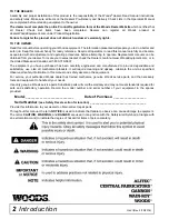
Страница 2: ...at www WoodsEquipment com or in the United States and Canada call 1 800 319 6637 The equipment you have purchased has been carefully engineered and manufactured to provide dependable and satisfactory...

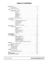
Страница 3: ...VICE 20 BLOCKING METHOD 20 LUBRICATION 21 BLADES 22 SLIP CLUTCH ADJUSTMENT 23 SHIELDING REPAIR 25 SERVICING TIRES SAFELY 25 CLEANING 26 TROUBLESHOOTING 27 DEALER SERVICE 28 DEALER SERVICE 28 GEARBOX M...

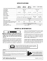
Страница 4: ...manual references are made to right and left directions These are determined by standing behind the equipment facing the direction of forward travel Blade rota tion is clockwise left wing and counter...

Страница 5: ...free at TheAEMStore https youtu be uEWXsDqhDq0 It reinforces the proper procedures to follow while operating your mowing equipment The video does not replace the information contained in the Operator...

Страница 6: ...wers Cutters English AEM Industrial Agricultural Mower Safety Manual English AEM Agricultural Tractor Safety Manual English Training Package for Rotary Mowers Cutters English Spanish Contains DVD VHS...

Страница 7: ...ir in hydraulic system by operating all hydraulic functions several times Do this before putting into service or allowing anyone to approach the equipment Make sure all hydraulic hoses fittings and va...

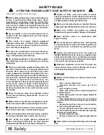
Страница 8: ...clear area of stones branches or other hard objects that might be thrown causing injury or damage TRANSPORTATION When transporting pay special attention to over head power lines and make sure the mach...

Страница 9: ...erating in reverse Do not operate or transport on steep slopes Do not stop start or change directions sud denly on slopes Watch for hidden hazards on the terrain during operation Do not handle blades...

Страница 10: ...hands Careless or improper handling may result in serious injury Your dealer can supply genuine replacement blades Substitute blades may not meet original equipment specifications and may be dangerou...

Страница 11: ...loth to clean safety decals Avoid spraying too close to decals when using a pressure washer high pressure water can enter through very small scratches or under edges of decals causing them to peel or...

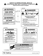
Страница 12: ...Safety MAN1281 4 15 2019 7 PN 15503 9 PN 18865 11 PN W19924 8 PN 18864 6 PN 18866 5 PN 15922 OR SAFETY INSTRUCTIONAL DECALS ATTENTION BECOME ALERT YOUR SAFETY IS INVOLVED Replace Immediately If Damag...

Страница 13: ...y 13 MAN1281 4 15 2019 SAFETY INSTRUCTIONAL DECALS ATTENTION BECOME ALERT YOUR SAFETY IS INVOLVED Replace Immediately If Damaged 12 PN 1045604 13 PN 1003751 15 PN 18964 16 PN 15502 14 PN 18877 10 PN 3...

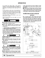
Страница 14: ...ch as 300 feet 92 m Never allow children or untrained persons to operate equipment Do not allow bystanders in the area when oper ating attaching removing assembling or servic ing equipment Make sure s...

Страница 15: ...e damage especially when turning CV Driveline Turning Limits NOTICE You must not exceed a turning angle of 80 degrees at the head of the Constant Velocity drive line or damage will occur 1 To check fo...

Страница 16: ...nd cutter CUTTER OPERATION Look down and to the rear and make sure area is clear before operating in reverse Do not operate or transport on steep slopes Do not stop start or change directions sud denl...

Страница 17: ...ry with attitude rod Experiment until you obtain the results you want When shredding attitude is set check that the distance from the bottom rear edge of the wing to the ground matches the bottom edge...

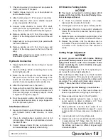
Страница 18: ...ck pin Figure 3 Figure 3 Transport Lock Pin Center Section Lock Up 1 Raise cutter with hydraulic cylinder to maximum height 2 Remove klik pin and lock pin from storage position Figure 5 Figure 4 Trans...

Страница 19: ...mechanism to prevent side to side movement ___ Check all lubrication points and grease as instructed in lubrication information Make sure the PTO slip joint is lubricated and that the gear box fluid...

Страница 20: ...D To minimize the potential hazards of working under neath the cutter follow these procedures Before performing any service or maintenance lower equipment to ground or block securely turn off engine r...

Страница 21: ...until oil is just above lower line on dip stick Check gearbox daily for evidence of leakage and contact your dealer if leakage occurs Use sealant on vent plug threads during installation Check vent pl...

Страница 22: ...ed in OWNER SERVICE must be done by a qualified dealership Special skills tools and safety proce dures may be required Failure to follow these instructions can result in serious injury or death Before...

Страница 23: ...x bearings Vibration may also cause struc tural cracks to cutter 1 Sharpen both blades at the same time to maintain balance Follow original sharpening pattern 2 Do not sharpen blade to a razor edge le...

Страница 24: ...nuts 12 5 If clutch does not slip freely disassemble and clean plates 4 6 7 flange yoke 1 and clutch hub 3 6 Reassemble clutch 7 Tighten Belleville spring 5 with nuts 11 until it is against the thrust...

Страница 25: ...Do not attempt to mount a tire unless you have the proper equipment and experience to perform the job Always maintain the correct tire pressure Do not inflate tires above the recommended pressure Neve...

Страница 26: ...debris such as clumps of dirt grass crop residue etc from machine Remove the remainder using a low pressure water spray 1 Be careful when spraying near scratched or torn safety decals or near edges o...

Страница 27: ...t height so blades do not frequently hit ground Excessive lush and tall vegetation Recut at 90 to first pass Excessive side skid wear Running with skids continuously on ground Raise cutting height or...

Страница 28: ...placing gears shafts and a housing is not cost effective Pur chasing a complete gearbox is more economical 2 Inspect gearbox for leakage and bad bearings Leakage is a very serious problem and must be...

Страница 29: ...nside housing 6 Remove oil seal 19 from front of housing to be replaced 7 Remove snap ring 10 and shim 13 from front of housing 2 8 Remove input bearing 7 by using a punch and hammer from outside of h...

Страница 30: ...2 2 lbs inch 16 Check that the gear backlash is between 0 006 and 0 016 You should not have to adjust the backlash 17 Press in input oil seal 19 using tube of correct diameter Be careful not to damage...

Страница 31: ...talled 2 Wash housing and all components thoroughly 3 Select a clean work area to assemble gearbox 4 Replace all seals bearings and gaskets 5 All parts must be clean and lightly oiled before assembly...

Страница 32: ...s heavy do not attempt to move it without mechanical assistance 1 Place gearbox on cutter and secure into position using four cap screws and lock washers 2 Torque hardware to 300 lbs ft 3 Attach all d...

Страница 33: ...with puller screw attach tube 5 to each clevis with bolts 2 and nuts 3 Place pad 4 in nut and thread puller screw 6 into nut from bottom Tighten until pad is solid against gearbox shaft For best resul...

Страница 34: ...17 Crossbar Assembly Installation UNIVERSAL JOINT REPAIR Figure 18 U Joint Exploded View U Joint Disassembly 1 Remove external snap rings from yokes in four locations as shown in Figure 19 Figure 19...

Страница 35: ...peat Step 1 and Step 2 to install remaining cups in remaining yoke 5 Move both yokes in all directions to check for free movement If movement is restricted rap on yokes sharply with a hammer to reliev...

Страница 36: ...ck stability Secure blocking prevents equipment from dropping due to hydrau lic leak down hydraulic system failures or mechanical component failures Do not disconnect hydraulic lines until machine is...

Страница 37: ...d insert blade pin through crossbar Make sure blade offset is to the bottom 3 Place blade 4 over blade pin with flat surface on the top 4 Install bushing 8 over pin and blade and secure with jam nut 9...

Страница 38: ...13 Do not tighten hardware 2 Attach stationary blade 5 to mounting bracket 6 using two cap screws 10 four hardened flat washers 915 and lock nuts 11 Blade should be angled by using the first hole on t...

Страница 39: ...mfered side of the lug nut toward the inside for steel rim for pneumatic tires and rims Tighten to 85 lbs ft Check that tire air pressure is a maximum of 40 psi NOTE Install the flat side of the nut t...

Страница 40: ...ow customer how to determine the turning lim its of the CV PTO driveline ___ Show customer the safe proper procedures to be used when mounting dismounting and storing equipment ___ Make customer aware...

Страница 41: ...SEMBLY 59 WING CENTER GEARBOX ASSEMBLY 60 61 CENTER DRIVE DECK ASSEMBLY 62 WING DRIVE ASSEMBLY 63 CROSSBAR ASSEMBLY 64 CENTER FRAME ASSEMBLY 66 67 WING ASSEMBLY 68 TONGUE ASSEMBLY 69 WING CENTER GEARB...

Страница 42: ...udes 11975 W11893 see page 51 for parts breakdown 7 11817 1 Hose 25 ID x 25 NPT x 230 8 11975 1 1 2 NPT vent plug 9 24098A 1 1 1 4 Cyl Strk Central Set 10 52201 2 Hose 25 ID x 25 NPT x 264 11 52204 2...

Страница 43: ...r spring arm ctr 13 611403RP 1 WA wheel yoke arm spring 14 1017149 1 Bar DR 1 25 x 8 85 15 1044932 1 Pin 1 00 x 11 50 16 1045655 1 Nut HFN 5 16 NC Dri Loc patch 17 1046049 2 Pin spirol 3 8 x 3 hvy ITE...

Страница 44: ...403RP 1 WA wheel yoke arm spring 16 611412RP 1 WA lower spring arm ctr 17 1017149 1 Bar DR 1 25 x 8 85 18 1044932 1 Pin 1 00 x 11 50 19 1045655 1 Nut HFN 5 16 NC Dri Loc patch 20 1046049 2 Pin spirol...

Страница 45: ...1019592 A R Gasket 15 mm 9 1019593 1019593 A R Gasket 25 mm 10 1019594 1019594 A R Gasket 45 mm 11 1019612 1019612 2 Hub cap 12 1019590 1019590 2 Oil seal 13 1019576 1019576 2 Output shaft 14 1019603...

Страница 46: ...16 1 Yoke and shaft CVSP lines 30 9 1000 RPM 6 1009065 2 Drive shield bearing kit 7 18864RP 1 Decal danger rotating driveline see page 12 8A 1021314 1 CV shield outer 540 RPM 8B 1021318 1 CV shield ou...

Страница 47: ...Wire harness 16 foot main 2 1040277 1 AG enhancer module 3 1045073 1 Wire harness rear 2 pieces includes both left right harnesses 4 1040276 1 LED AG combo lamp right 5 1040275 1 LED AG combo lamp lef...

Страница 48: ...NC x 1 carriage bolt GR5 17 14350 3 8 NC flanged lock nut 18 1027189 1 Rear chain plate center short 19 1007852 1 Pin 7 to 9 chains REF PART QTY DESCRIPTION 1 1029881 1 Front center chain plate 2 102...

Страница 49: ...2 carriage bolt GR5 15 11900 1 2 NC flanged lock nut 16 6697 3 8 NC x 1 carriage bolt GR5 17 14350 3 8 NC flanged lock nut REF PART QTY DESCRIPTION 1 1029885 1 Front wing chain plate inner 2 1029884...

Страница 50: ...m for pneumatic tire 5 bolt OR 16 1017040 1 6 00 x 9 solid tire rim hardware 5 bolt OR 16 1039976 1 25 x 8 x 14 severe duty ag tire rim hardware 5 bolt OR REF PART QTY DESCRIPTION 16 1039976F 1 25 x 8...

Страница 51: ...on seal 2G 1 Piston o ring 3 N S N S 1 Cylinder housing rod end 4 N S N S 1 Piston 5 N S N S 1 Jam nut 6 N S N S 4 Cylinder tie rod 7 3 1 2 Pipe plug 8 N S N S 1 Cylinder housing butt end 9 N S N S 2...

Страница 52: ...includes items 2A 2F 2A 2 Cap o ring 2B 1 Piston seal 2C 1 Rod o ring 2D 1 Cap seal 2E 1 Wiper seal 2F 2 Backup seal 3 N S 1 Cylinder housing rod end 4 N S 1 Piston 5 N S 1 Jam nut 6 N S 4 Cylinder t...

Страница 53: ...nt 3 1 1 1 4 segment 4 1 1 segment 5 1 3 4 segment REF PART QTY DESCRIPTION A 8811 1 Crossbar puller complete 1 19914RP 2 Crossbar puller clevis 2 3097 4 5 8 NC x 4 1 2 HHCS GR5 3 230 4 5 8 NC hex nut...

Страница 54: ...3 12 x 3 25 x 10 00 12 12612 1 Gear winch 5 1 to 1 13 12642 1 Winch cable clamp kit 14 11790 1 C Hook 1 4 cable 15 52479 1 Cable 1 4 x 24 ft 16 11789 2 Clip 1 4 cable 17 839 HHCS 3 8 NC x 1 GR5 18 56...

Страница 55: ...Common Components 55 MAN1281 4 15 2019 NOTES...

Страница 56: ...56 50 Series Parts MAN1281 4 15 2019 CENTER FRAME ASSEMBLY BW20 50 BW20 50Q...

Страница 57: ...S 5 8 NC x 3 3 4 GR5 ZP 23 609904 1 Pin 1 25 x 7 00 REF PART QTY DESCRIPTION 24 1003828 1 Manual tube 25 1004251 1 SMV bracket 26 1017055 5 Flag pin 1 25 x 6 5 27 1017143RP 1 Lug bent 25 x 2 25 x 11 0...

Страница 58: ...t wing 7 1027099RP 1 BW240 skid LT left wing 8 1027120RP 1 WA wing gearbox shield BW240 9 1027246RP 1 Angle RT wing right wing 10 1027247RP 1 Angle LT wing left wing 11 1041071 4 Screw HFS M8 1 25 x 1...

Страница 59: ...4 x 1 x 9 16 HT 4 13759 3 HHCS 3 4 NC x 2 1 4 GR5 ZP 5 19407 1 Asy safety chain 10 000 lb 6 28873 2 Washer 3 4 ID 1 1 2 OD 1 4 thick 7 46605 2 Pin CLV 1 00 x 2 26 8 52232 1 Swivel parking jack 9 1005...

Страница 60: ...60 50 Series Parts MAN1281 4 15 2019 WING CENTER GEARBOX ASSEMBLY BW20 50 BW20 50Q...

Страница 61: ...13 2 57471 57471 57471 57471 Shim 70 3 x 84 7 14 1 57329 57329 57329 57329 Castle nut M40 x 1 5P 15 1 39323 39323 39323 39323 Castle nut M30 x 2 0P 16 1 57471 57471 57471 57471 Shim 50 3 x 70 3 17 1 5...

Страница 62: ...ng 5 57416 1 Friction clutch 1340 1 3 4 20 spline 6 57438 1 Flange yoke 7 57432 2 Friction disc 8 57440 1 Hub 1 3 4 20 spline REF PART QTY DESCRIPTION 9 57434 1 Thrust plate 10 57439 1 Belleville spri...

Страница 63: ...1679 1 Support bearing 12 1045593 1 Inner shield 13 1045595 1 Profile and sleeve 14 33347 1 Decal Danger Guard Missing REF PART QTY DESCRIPTION 15 40779 1 Grease fitting 16 44677 1 Inboard yoke S5 17...

Страница 64: ...2 GR5 ZP 2 8820KT 1 Kit blade 8820 STD 3 8825KT 1 Kit blade 8825 STD 4 10520RP 2 18 GA 1 1 2 blade pin shim 5 13946RP 2 20 GA 1 1 2 blade pin shim 6 32603 2 Keyhole plate special 7 32604RP 2 Blade pi...

Страница 65: ...50 Series Parts 65 MAN1281 4 15 2019 NOTES...

Страница 66: ...66 60 Series Parts MAN1281 4 15 2019 CENTER FRAME ASSEMBLY BW20 60 BW20 60Q...

Страница 67: ...0451 6 HHCS 5 8 NC x 3 3 4 GR5 ZP REF PART QTY DESCRIPTION 23 609904 1 Pin 1 25 x 7 00 24 1003828 1 Manual tube 25 1004251 1 SMV bracket 26 1017055 5 Flag pin 1 25 x 6 5 27 1017143RP 1 Lug bent 25 x 2...

Страница 68: ...skid RT right wing 8 1027099RP 1 BW240 skid LT left wing 9 1027120RP 1 WA wing gearbox shield BW240 10 1027246RP 1 Angle RT wing right wing 11 1027247RP 1 Angle LT wing left wing 12 1041071 4 Screw HF...

Страница 69: ...2 NC x 1 1 2 HT 10 52232 1 Swivel parking jack 11 52442RP 1 Bracket CV hose holder 12 65130 2 Pipe 1 SCH 40 x 1 00 13 301014 1 Bolt mach 3 4 NC x 9 14 611434RP 1 WA tongue BW20 15 1017045 1 Flag pin...

Страница 70: ...70 60 Series Parts MAN1281 4 15 2019 WING CENTER GEARBOX ASSEMBLY BW20 60 BW20 60Q...

Страница 71: ...ng 85 UNI7437 11 1 57321 57321 57321 57321 57321 57321 Snap ring 50 UNI7435 12 1 57456 57456 57456 57456 57456 57456 Shim 45 3 x 2 5 13 2 57471 57471 57471 57471 57471 57471 Shim 70 3 x 84 7 14 1 5732...

Страница 72: ...ng 5 57416 1 Friction clutch 1340 1 3 4 20 spline 6 57438 1 Flange yoke 7 57432 2 Friction disc 8 57440 1 Hub 1 3 4 20 spline REF PART QTY DESCRIPTION 9 57434 1 Thrust plate 10 57439 1 Belleville spri...

Страница 73: ...679 1 Support bearing 12 1045593 1 Inner shield 13 1045595 1 Profile and sleeve 14 33347 1 Decal danger guard missing REF PART QTY DESCRIPTION 15 40779 1 Grease fitting 16 44677 1 Inboard yoke S5 17 1...

Страница 74: ...1 Kit blade 8820 STD 3 8825KT 1 Kit blade 8825 STD 4 10520RP 2 18 GA 1 1 2 blade pin shim 5 13946RP 2 20 GA 1 1 2 blade pin shim 6 32603RP 2 Keyhole plate special 7 32604RP 2 Blade pin lock clip spec...

Страница 75: ...128KT 6 Blade 5 x 4 x 22 5 flat 5 39089 3 Blade 38 x 4 x 11 13 double edge 6 1014164 2 Mounting bracket bent 7 39069 6 Blade pin REF PART QTY DESCRIPTION 8 39127 6 Bushing 9 39128 6 Jam nut 1 1 4 10 4...

Страница 76: ...76 70 Series Parts MAN1281 4 15 2019 CENTER FRAME ASSEMBLY BW20 70 BW20 70Q BW13 70 BW13 70Q BW13 70QREV...

Страница 77: ...1003828 1 Manual tube REF PART QTY DESCRIPTION 24 1004251 1 SMV bracket 25 1017055 1 Flag pin 1 25 x 6 5 26 1017143RP 1 Lug bent 25 x 2 25 x 11 0 27 1019600 1 Plug breather M18 x 1 5 28 1019607 1 Asy...

Страница 78: ...1027098RP 1 BW240 skid RT right wing 8 1027099RP 1 BW240 skid LR left wing 9 1027120RP 1 WA wing gearbox shield BW240 10 1027246RP 1 Angle RT wing right wing 11 1027247RP 1 Angle LT wing left wing 12...

Страница 79: ...3 2 Bolt crg 1 2 NC x 1 1 2 HT 10 52232 1 Swivel parking jack 11 52442RP 1 Bracket CV hose holder 12 65130 2 Pipe 1 SCH 40 x 1 00 13 301014 1 Bolt mach 3 4 NC x 9 14 611434RP 1 WA tongue BW20 15 10170...

Страница 80: ...80 70 Series Parts MAN1281 4 15 2019 WING CENTER GEARBOX ASSEMBLY BW20 70 BW20 70Q BW13 70 BW13 70Q BW13 70QREV...

Страница 81: ...5 Bearing adjustment nut 19 1 1 8 x 2 1 2 cotter pin 20 3 1019587 1019587 1019587 1019587 1019587 1019587 Bearing assembly cup cone 21 1 1019615 1019615 1019615 1019615 1019615 1019615 Blank adjustmen...

Страница 82: ...1 Friction clutch 2400 1 3 4 20 spline 6 1016489 1 Flange yoke 7 57432 4 Friction disc 8 1016490 1 Hub 1 3 4 20 spline clutch 9 1016498 1 Lock assembly 10 57443 1 Drive plate REF PART QTY DESCRIPTION...

Страница 83: ...9 11 13 1029843 1 Outer profile sleeve includes items 14 15 14 33347 1 Decal danger guard missing 15 40779 1 Grease fitting 16 40751 1 Inboard yoke REF PART QTY DESCRIPTION 17 1019109 1 Friction clutc...

Страница 84: ...S 1 2 NC x 1 1 2 GR5 ZP 2 8820KT 1 Kit blade 8820 STD 3 8825KT 1 Kit blade 8825 STD 4 10520RP 2 18GA 1 1 2 blade pin shim 5 13946RP 2 20GA 1 1 2 blade pin shim 6 32603 2 Keyhole plate special 7 32604R...

Страница 85: ...28KT 6 Blade 5 x 4 x 22 5 flat 5 39089 3 Blade 38 x 4 x 11 13 double edge 6 1014164 2 Mounting bracket bent 7 39069 6 Blade pin REF PART QTY DESCRIPTION 8 39127 6 Bushing 9 39128 6 Jam nut 1 1 4 10 45...

Страница 86: ...Front double chain shield bracket left weight box OR 5 1027065 1 Front double chain shield bracket right weight box 6 1027135 2 Bracket Chain weight box OR 6 1029894 2 Bracket double chain weight box...

Страница 87: ...1 2 467 634 722 979 1020 1383 Diameter Thread Pitch Millimeters Wrench Size COARSE THREAD FINE THREAD Diameter Thread Pitch Millimeters MARKING ON HEAD MARKING ON HEAD Metric 8 8 Metric 10 9 Metric 8...

Страница 88: ...HHCS Hex Head Cap Screw HT Heat Treated JIC Joint Industry Council 37 Degree Flare LH Left Hand LT Left m Meter mm Millimeter M Male MPa Mega Pascal N Newton NC National Coarse NF National Fine NPSM...

Страница 89: ...roduct Registration 2 Specifications 4 Table of Contents 3 Warranty Product 91 Replacement Parts 90 OPERATION Connecting Cutter to Tractor 14 Cutting Height Adjustment 15 CV Driveline Turning Limits 1...

Страница 90: ...product must be returned to WOODS with proof of purchase within thirty 30 days after such defect or noncompliance is discovered or should have been discovered routed through the dealer and distributo...

Страница 91: ...r replacement free of charge of the product if WOODS in its sole discretion deems it to be defective or in noncompliance with this Warranty The product must be returned to WOODS with proof of purchase...

Страница 92: ...ames or service marks not owned by Woods Equipment Company that appear in this manual are the property of their respec tive companies or mark holders Specifications subject to change without notice WO...

Отзывы: