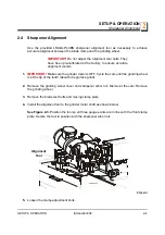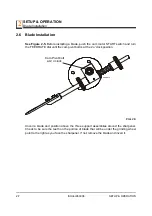
SETUP & OPERATION
Blade Support Installation
SETUP & OPERATION
ISHdoc063008
2-2
2
Have a qualified electrician make the power supply. The power supply must meet
the specifications given below.
2.2
Blade Support Installation
The sharpener includes three blade support arms with guide assemblies.
To install the support arms, lubricate the threaded ends of the arms with grease. Insert
one arm into the threaded holes on each side of the sharpener.
1.
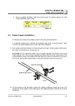
Each guide assembly consists of a blade support with post, a blade support without post,
two bolts, a self-locking nut, and a wing nut.
See Figure 2-1.
To install the guides, join one guide assembly around the end of each
blade support arm. Face the post outward as shown. Bolt from the hexed side of the
guide assembly (these hex-shaped holes will keep the bolts from turning once in place).
Secure the top bolt with a self-locking nut. Secure the bottom bolt with a wing nut.
2.
Tilt the guides on the left blade support arm slightly backward, toward the rear of the
sharpener. Tilt the guides on the right support arm slightly forward, toward the front of the
sharpener.
2-Phase
Volts
Fuse [A]
Suggested Wire
Size
230 VAC
10 A
1.5 mm at least
2
TABLE 2-0
Support Assembly
Blade Support Arm
CESH04


