


12
Figure 22
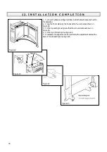
Figure 21
2. Fit the sides to the engine unit case with two machine screws and washers per side. See
figure 21.
3. For appliance side switch
Fit the switch mounting bracket to the right side casting with two thread cutting screws
supplied. The leads should hang down from the connectors at back of the switch so that
pressing the upper half of the switch rocker turns the fire up. See figure 22.
8 .
G A S S U P P L Y I N S T A L L A T I O N
1. Extend the gas supply pipe to a convenient point and connect it to the inlet pipe at the
rear left corner of the stove. The connection is Rp1/4 (1/4in. B.S.P).
The supply pipe must be of rigid material (e.g. copper). Flexible connections must not
be used.
2. Provision for isolation of the gas supply upstream of the fire must be provided for
safety and servicing.
3. Pressure test the installation for gas soundness in accordance with the current edition
of B.S.6891.


