7. There are two holes in the metal rim of the LED head. Use the metal rim as a template and mark the two
holes locations on the light assembly housing and drill to size using an 1/8” drill.
8. Clean the interior of light assembly and lens of any dust or filings, which may have developed during cutting
the hole.
9. Re-install the OEM factory light assembly and reflector.
10. Place the rubber gasket around the LED head
and install the head into the one (1) hole and
secure using the self-tapping screws
(provided).
11. Repeat the same installation procedure for
the remaining LED heads.
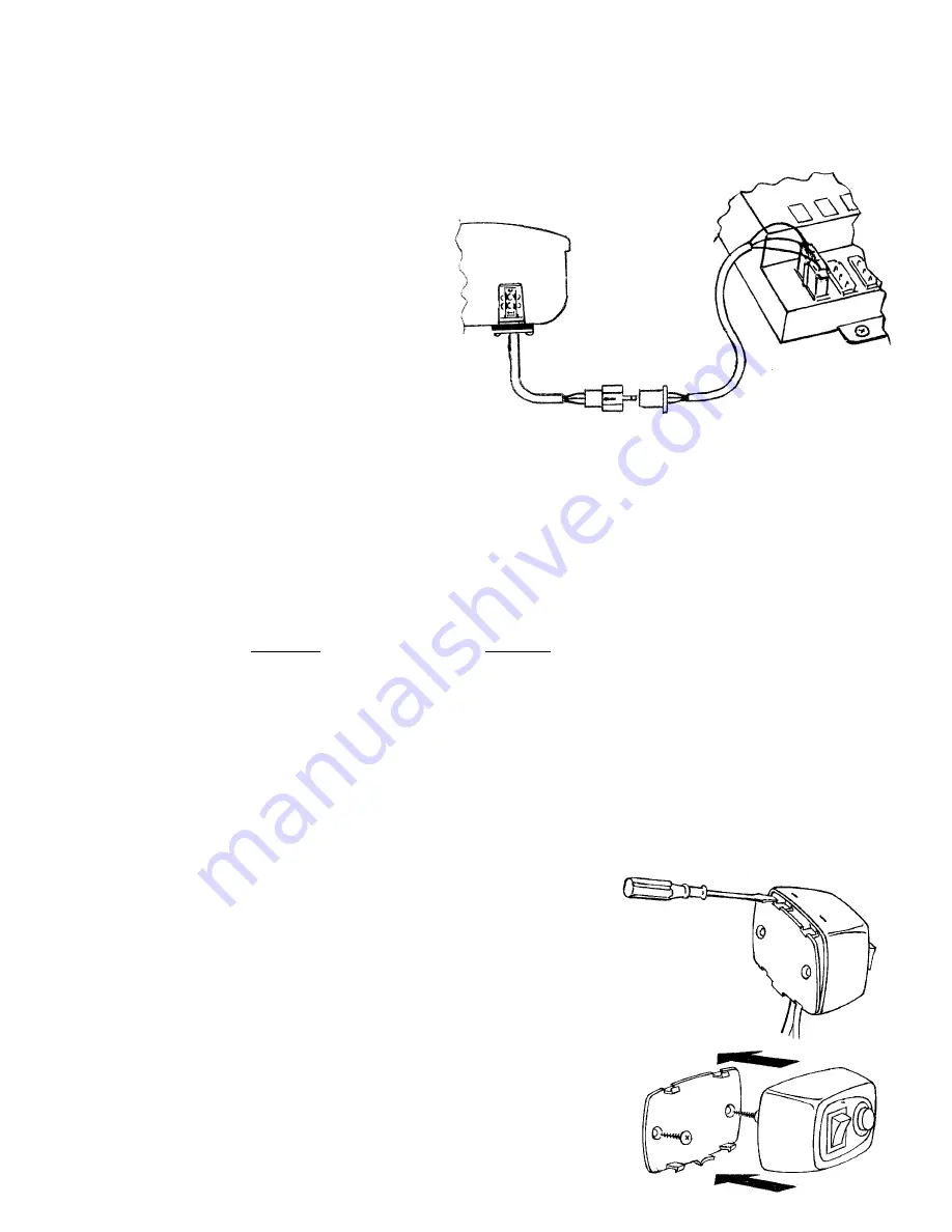
WIRING LED HEADS Fig. C
IMPORTANT: To prevent damage to the power
supply, DO NOT connect any power source until
all of the LED heads are completely wired to the
power supply. All 8504 models come with four (4)
cables that are used to connect the LED heads to
the power supply. Each cable has two female plugs, one at each end. The plugs are different and will only
connect to its mate, either the LED head, or power supply.
12. Two of the cables are 3 meters / 9.8 ft. in length and should be used to connect the LED heads installed in
the front light assemblies to the power supply position L1 & L2.
13. Two of the cables are 5 meters / 16.4 ft. in length and should be used to connect the LED heads installed
in the rear light assemblies to the power supply position L3 & L4.
NOTE: If you need to lengthen the rear cables, see chart below for proper wire gauge.
16-30 ft.
31-50 ft.
Use 18 Gauge or heavier
Use 16 Gauge or heavier
MOUNTING SWITCH CONTROL PANEL
Using double face tape or screws
TAPE METHOD
14. Select a mounting location for the control panel that is easy to reach. IMPORTANT: Be sure that the switch
control panel or its wires will not interfere with air bags or the driver’s vision.
15. Using the double-sided foam adhesive tape provided, mount the control panel to selected location. Make
sure that mounting surface is free from dust, wax etc. A clean surface is necessary so that double-sided
tape will hold properly.
IMPORTANT: THE ADHESIVE HOLDING POWER BECOMES
MAXIMUM IN ABOUT 24 HOURS. LIMIT MOVING OR PUTTING
PRESSURE ONTO THE KEYBOARD UNTIL THEN.
SCREW METHOD Fig. D & E
16. Remove the control panel’s backing plate using a flat tip screwdriver.
17.Using the backing plate as a template, mark the two hole locations
onto the mounting surface where the switch panel will be mounted and
drill to size using a 3/16” drill. IMPORTANT: The installer must
carefully inspect both sides of the mounting location before drilling any
holes to ensure that there are no components, wires and or any
vehicle part that could be damaged by drilling.
18. Position the backing plate on the mounting surface and secure using
the two sheet metal screws provided that have the countersunk head.
19. The control panel is carefully pushed onto the backing plate.
Fig. C
Fig. D
Fig. E
HOLE SIZE
3/16”


