background image

18

3064058_201610

AHU TE

AHUW TE

Installation instructions

Piggyback units

(air intake/exhaust air units 

stacked one on top of the other)

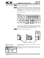
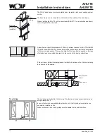
Piggyback units supplied with top and bottom units separated must be securely connected 

on site (after the units have been positioned) and sealed tight on the whole perimeter 

against rainwater penetration by means of a permanently elastic seal (weatherproof 

version AHUW TE).

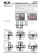
Units are secured by means of fixing elements and Self-drilling/tapping screw 5,5x19 

on the outside, as shown (on site).

The requisite number of fixing elements is supplied with the air-handling unit.

Only secure the top and bottom units together 

after

 the individual cubes unit and the 

top and bottom units have been assembled.

If required, install permanently resilient sealing strips or plastic sealing profiles before 

lowering the top unit into position on the bottom unit.

AHUW TE projection

AHUW TE view

AHUW TE projection

AHUW TE 450-1000

Projection

Self-drilling/ 

tapping screw  

5.5 x 19

Sealing tape

View A

Projection

Self-drilling/ 

tapping screw  

5.5 x 19

Sealing 

tape

View B, C, D

Projection

Roof

Sealing tape

View E

AHUW TE 21-380

Projection

Self-drilling/ 

tapping screw  

5.5 x 19

Sealing tape

View A

Projection

Roof

Self-drilling/ 

tapping screw  

5.5 x 19

Sealing tape

Sealing tape

View E

View B, C, D

Self-drilling/ 

tapping screw  

5.5 x 19

Sealing tape

Projection

Содержание AHU TE

Страница 1: ...84048 MAINBURG TEL 49 0 875174 0 FAX 49 0 875174 1600 www WOLF eu Art Nr 3064058_201610 Subject to technical modifications GB Installation and maintenance instructions Air handling unit AHU TE AHUW TE Translation of the original ...

Страница 2: ...on 31 Shutdown Fire 32 End of life disposal 32 Checklist 33 For type of device serial number and order number see type plate on the equipment Order related device specifications such as weights dimensions sound data spare parts energy data etc are to be taken from the order data sheets Original Wolf spare parts can be procured at short notice stating the order number on the type plate by fax to 00...

Страница 3: ... ISO 1940 1 Mechanical vibration balance quality DIN EN 60335 1 Safety of electrical appliances for domestic use and similar purposes DIN EN 13053 Ventilation of buildings central ventilation appliances Section 6 Performance characteristics for appliances components and assemblies VDMA 24167 Fans safety requirements RLT Guideline 01 VDI 3803 Technical requirements for ventilation appliances Sectio...

Страница 4: ...ag filter section Heater section KGXD section KGX section Empty section Empty section with damper Empty section with damper and tray Empty section with tray Silencer section Humidifier section Heater section with frost protection frame Cooling section Rotary heat ex changer section GS PWT section ...

Страница 5: ...s that must be complied with to prevent equipment damage and malfunctions In addition to the installation and maintenance instructions labels affixed to the equipment bear information Compliance with these too is mandatory Note The persons tasked with installation commissioning maintenance and operation of the air handling unit must be adequately qualified and must have received suitable instructi...

Страница 6: ...ntains any constituents that are inju rious to health inflammable explosive aggressive corrosive or dangerous in any other way since these substances can otherwise be spread throughout the duct system and the building and impair the health of people animals or plants living there or even kill them Air conditioning units for the transport of inflammable or explosive gases must be specially designed...

Страница 7: ...appliances with slings Tall appliances on a small footprint e g RWT are connected with an increased risk of tipping over during unloading and handling on site This requires additional measures on site to prevent tipping over e g securing with straps If a forklift or rollers are used to move the units always ensure that the forks or rollers are located underneath the frame sections at all times so ...

Страница 8: ...r installation operation and maintenance see the table below Footprint of space required for installation operation and maintenance Fan section 0 8 x appliance width Cooling coil heating coil KVS 1 x appliance width 250 mm Filter section up to AHU TE 96 1 x appliance width from AHU TE 130 0 5 x appliance width In back to back configurations with side by side units leave clearances as stated above ...

Страница 9: ... errors and installation inaccuracies Appliance example top view Note Note When installing high or perhaps smaller appliance components e g RWT RWT duct components or standing appliance layouts with several components above each other secure these during assembly installation against tipping until they are finally connected to other components that ensure that tipping is prevented Requires permane...

Страница 10: ...e on which the units and components are to be assembled and installed is level horizontal and of adequate load bearing capacity The base frame must be horizontal and the foundation must be level and horizontal check with browning rod To prevent the inspection doors from jamming the lower base frame must make full surface contact with the base pad or point contact is not permissible Provide a perma...

Страница 11: ...e base frame pitch and the appliance pitch match when appliances with pre installed base frames are split for shipping Support bracket item 6 in case of factory fitted base frame if different weights lead to an offset at cube joints assembly on site 6 6 Insulating strip fitted on site Insulating strip fitted on site Offset Connecting brackets items 4 and 5 if air conditioning units are positioned ...

Страница 12: ...ions The WOLF base frame must be insulated and integrated into the roof sealing system on site The base frame can be insulated on the inside or the outside of the base frame When installing the AHU TE on its own stands AHUW TE on an on site base frame secure it against the wind load Drop ledge Structure borne sound insulation Short sections of duct Base frame Roof The tray bridge is already fitted...

Страница 13: ... dip both ends of the vertical hollow section approx 2 mm deep into the sealant The appliances are assembled in reverse order Appliances that can be dismantled The equipment is shipped to site preassembled It can be disassembled before being moved into position and reassembled at the final location Disassembly entails removing the casing and carefully removing internal components such as heating o...

Страница 14: ...se and must be installed on site once the air handling unit has been assembled and installed The requisite fasteners and sealing materials are supplied with the appliance The lifting eyes can remain in the unit as sealed in the factory Roof Use a plastic headed mallet to tap the cover strip into place Note Pack space of sealing strip with sealing compound Installation instructions The roofs of the...

Страница 15: ...sories inside identifies the component in question AHU TE 21 380 Self drilling tapping screw X 6 3 x 90 Mat no 3490238 AHU TE 450 1000 Self drilling tapping screw X 6 3 x 120 Mat no 3490252 Self drilling tapping screw Self drilling tapping screw with washer Appliance connection bracket Part no 6616824 X 6 3 x 62 Mat no 3480031 Self drilling tapping screws Appliance connection bracket Part no 66168...

Страница 16: ... on the outside the units in question can be connected but under no circumstances can the assembly be moved as a single unit Note External appliance connection Tensioning straps may be used to make the assembly of the cube units easier Position the appliance parts next to each other and close the gap between them with tensioning straps Then bolt the components together by means of the connectors s...

Страница 17: ... Fixing elements M8 screw When tightening screws and nuts always counterhold with a second open ended spanner Internal appliance connection The individual transport units can always be lifted and transported when units are joined internally Variant 1 Variant 2 ...

Страница 18: ...ir handling unit Only secure the top and bottom units together after the individual cubes unit and the top and bottom units have been assembled If required install permanently resilient sealing strips or plastic sealing profiles before lowering the top unit into position on the bottom unit AHUW TE projection AHUW TE view AHUW TE projection AHUW TE 450 1000 Projection Self drilling tapping screw 5 ...

Страница 19: ...use bends to make the connections Thisconfigurationwillensurethattheheatexchangerandthemisteliminator can be extracted to one side for subsequent cleaning Always install steam registers so that the steam inlet is always at the top large diameter connector and the condensate drain is always at the bottom When connecting the flow and return lines always use a wrench of correct size to counterhold th...

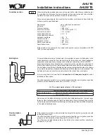
Страница 20: ...on on site Ball siphon h Never connect the siphon discharge directly to the wastewater system Instead leave the end of the discharge open so that it can drain freely Long discharge lines must be vented to prevent condensate from backing up in the pipe provide an additional opening in the siphon discharge pipe To permit reliable draining of condensate it is important to connect a ball siphon to the...

Страница 21: ...Top section Screws Assemble the side panels and top section as shown using the screws supplied For a configuration with two or three intake discharge hoods one above the other the upper hood overlaps the lower hood Overlap Versions AHU TE 21 210 AHU TE 270 380 AHU TE 680 AHU TE 450 600 AHU TE 850 1000 AHU TE 680 1000 ...

Страница 22: ...velop its rated output and may be destroyed Use a PTC thermistor trigger for each motor with PTC thermistor an interlock contactor for each motor with thermo contacts and a thermal overcurrent relay for each motor without PTC thermistor or thermistor contacts Useequipotentialbondingandearthstrapstoensuretheprotectiveconductorconnection between the air handling unit and the ducts and between the he...

Страница 23: ...as Dahlander pole changing circuit Wiring for 1500 3000 rpm or 750 1500 rpm for example Low speed High speed Contactor control Pole change over switch Use Windings for stepped output in accordance with a torque sequence for fan drive Wiring for three speeds 2 separate windings 1 as Dahlander pole changing circuit Wiring for fan drives 500 1000 1500 rpm or 500 1000 rpm as Dahlander pole changing ci...

Страница 24: ...the ducts are connected and the inspection doors are closed Failure to comply with this requirement will give rise to the risk of motor overload Switch on the main isolator Briefly start the drive motor and check the fan impeller direction of rotation Correct the direction of rotation if necessary Proceed with extreme caution at all times as the door of the fan section must be open for these opera...

Страница 25: ... direction of rotation of the drive motor s of the damper s is correct if required reverse the direction of rotation switch on the servomotor If necessary louver dampers must be insulated by the customer to prevent noise emis sions and the formation of condensation water or heat losses If the unit is fitted with dampers comply with the separate installation instructions for the damper positioning ...

Страница 26: ...y temperature limiter Ensure that at least one safety temperature limiter is installed at the top inside of the heating coil Ensure that the electric heating register is protected against humidity and water Note Note Electric heating coil To prevent overheating ensure that the air flow rates comply with the minimum value specified below figures are in m h Appliance type AHU TE AHUW TE 21 43 64 96 ...

Страница 27: ... is a risk of ice forming on the fins of the heat exchanger obstructing or preventing the air flow The direct expansion evaporator will be unable to achieve its rated performance unless the refrigerant used is the same as that on which the design was based R22 or R134a Never permit refrigerant to escape to the environment as otherwise there is a risk of environmental pollution Use a vacuum extract...

Страница 28: ...he fixing screws of the square sections and undo the locknuts on the tensioning screw Tighten the tensioning screw until the belt is correctly tensioned ensuring that the vee belt pulleys remain in perfect alignment Tighten the locknuts and the fixing screws Check that the vee belt pulleys are in perfect alignment Note Vee belt tensioning screw appliance with motor carrier Fan section Fan bearings...

Страница 29: ... SPA 100 132 140 200 224 315 20 27 28 35 35 50 SPB 180 224 236 315 315 400 400 500 40 52 46 60 55 76 67 90 Deflection x mm Axis clearance A mm Flat belt drive Check the precise parallelism of the fan drive shaft to the motor drive shaft Check the precise alignment of the pulleys Clean the pulley belt faces thoroughly to remove dirt oil and grease Using a pencil apply measuring marks to the belt at...

Страница 30: ...rrunthepumpdry Note Note Filter Wear protective clothes protective gloves and a respirator when exchanging the filter Contaminated filters are dangerous to human health Contact with filter dust can cause allergic reactions of the skin eyes and respiratory organs If filter inserts require cleaning or replacement open the inspection door and pull them to the side and out of the casing Category G4 sy...

Страница 31: ...d air to blow out residual water Plate type heat exchanger with bypass operate in bypass mode to defrost Steam coil When the heating system is shut down drain all water retaining parts and use compressed air to blow out residual water Electric heating coil No frost protection measures required Scrubber section Insulate the water supply pipe on site install pipe ribbon heater if required Drain the ...

Страница 32: ...ontaining antifreeze refrigerant etc professionally in accordance with local regulations The system can then be disassembled into its component parts Metal and plastic parts must be sorted and disposed of in the correct environmentally responsible manner weight reduction Be aware that load bearing metal and plastic components may have aged and thus no longer reach the original structural load limi...

Страница 33: ...age 3 Steam humidifier Wash with cleaning agents Rinse and dry the humidifier chamber disinfect if necessary 6 Check steam wand for deposits Clean 6 Check hygiene condition 6 Heat exchanger Check for contamination damage and corrosion Clean and repair 3 Check siphon function Repair 3 Check hygiene condition 6 Fan Check for contamination damage and corrosion Clean and repair 6 Heat recovery Check c...

Страница 34: ...34 3064058_201610 AHU TE AHUW TE ...

Страница 35: ...35 3064058_201610 AHU TE AHUW TE ...

Страница 36: ...Wolf GmbH Postfach 1380 D 84048 Mainburg Tel 49 8751 74 0 Fax 49 8751 741600 Internet www wolf heiztechnik AHU TE AHUW TE 3064058_201610 Subject to technical modifications ...

Отзывы: