15
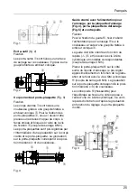
Tool holders
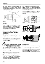
(Fig. 2)
Mounting
The tool holders
6
are fastened on a
clamping surface using a threaded taper
pin
5
in the slider.
Serrated tool bodies and insert holders
(Fig. 3)
Mounting
The serrated tool bodies
7
are fastened
in the slider using a threaded taper pin
5
.
To fasten the insert holders
8
in place,
they are mounted onto the K-profi le of the
serrated tool body and clamped using the
fi xing screw
9
(tightening torque 8 Nm
(70.81 in. lbs.)). The insert holders can be
preset using the scale on the serrated tool
body and insert holders. The scale on the
insert holder is valid for a center slider
position (= 0).
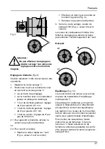
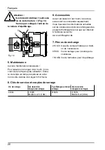
Serrated slide with coolant delivery
section, insert holder for boring (Fig. 4),
insert holder for outside turning (Fig. 5)
and counterweight
Mounting
To fasten the serrated slide
0
the coolant
delivery section 11 is fastened using a
threaded taper pin
5
in the slider.
The serrated slide is aligned according to
the marking ( )
“
and fastened in place
using the cap screws with washer. (tighte-
ning torque 4 Nm (35.40 in. lbs.)).
Insert holder
„
is mounted on the side with
the coolant delivery section, roughly preset
according to the scale and then fastened
in place using cape screw
”
(tightening
torque 8 Nm (70.81 in. lbs.)). The scale on
the insert holder is valid for a center slider
position (= 0).
The balancing counterweight
¿
is fastened
on the opposite side using a cap screw.
This counterweight must be fastened in
place to match the scale setting for the
mounted insert holder.
English
Fig. 1
Fig. 2
Fig. 3
Fig. 4
3
4
5
5
7
5
8
9
6
5
0
ß
„
”
“
¿
Содержание VARIOBORE 536
Страница 1: ......


