background image

17


Notice:

Do not make any diameter 

adjustments in the clamped 

state! The adjustment parts 

could be damaged otherwise.

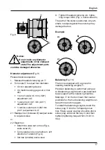
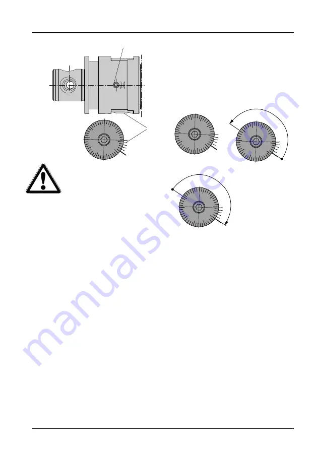
Diameter adjustment

 (Fig. 9)

Please observe sequence:
1.  Release threaded clamping pin 

1

2.  Turn scale 

2

 to adjust tool diameter.


•  On tool presetting device


•  On machine using gage cut or trial 

drill


•  1 turn of scale: 0.5 mm (.020“)  

adjustment in Ø


•  1 scale mark: 0.01 mm (.001“)  

adjustment in Ø


•  1 vernier scale mark: 0.002 mm 

(.001“) adjustment in Ø

2.1 Readjust tool (increase Ø) readjust scale 

to required value

or
2.2 Reset tool 
 

•  Determine value set on tool (Fig a, 

scale value 21)


•  Turn scale back by one half-turn, left 

direction of rotation (Fig. b)


•  Set new (smaller) scale value

3.  Tighten threaded clamping pin, tighte-

ning torque 3 Nm (Fig. c, scale value 20)

The path of the slider is restricted. Any att-

empts to adjust against the end stop may 

damage the tool.

20

30

10

0

40

10

15

5

0

a)

20

30

10

0

40

10

5

0

15

b)

Example:

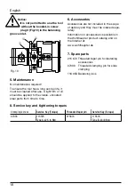
Balancing 

(Fig. 10)

The tool is equipped with a groove for 

inserting balancing weights 

1

.

Precision balancing is performed using up 

to 6 balancing weights and a pre-balanced 

basic support with a balancing machine.
Markings 

on the tool mean that neutral 

positions for the four balancing weights can 

be set time and time again.
To install the balancing weights, insert the 

screw plug 

3

 into the T-shaped groove 

first. Finally, apply coating of Loctite 234 to 

screw plug, screw all the way in and then 

tighten (tightening torque 8 Nm (70.81 in. 

lbs.))

Fig. 9

2

20

30

10

0

40

10

15

5

0

20

30

10

0

40

10

15

5

0

c)

English

1

Содержание VARIOBORE 536

Страница 1: ......

Страница 2: ...ehebung 10 English 12 Français 22 Wohlhaupter Werkzeuge unterliegen einer ständigen technischen Weiterent wick lung Aktuelle Informationen erhal ten Sie aus unseren Produkt Katalogen sowie im Internet unter www wohlhaupter com Wohlhaupter tools are subject to constant further technical development You can obtain up to date information from our product catalogue as well as on our website www wohlha...

Страница 3: ...ung und Betrieb Das Feindrehwerkzeug ist zur Bearbeitung von Bohrungen ab Ø 0 4 mm bis Ø 152 mm vorgesehen Für die einzelnen Durchmesserbereiche steht ein umfangreiches Zubehör Pro gramm zur Verfügung Ausdrehen Für den Bereich Ø 0 4 6 5 mm Mini Ausdrehprogramm Für den Bereich Ø 6 27 mm Klemmhalter aus Stahl bzw Hartmetall Für den Bereich Ø 20 53 mm Plattenhalter mit Kerbzahnkörpern aus Stahl bzw H...

Страница 4: ...instell bar und werden mit einem Kegelgewin destift 5 an der Spannfläche gespannt Dabei ist eine Mindesteinspannlänge zu beachten Maximal zulässige Drehzahlen gültig für zugehöriges Original Wohlhaupter Zubehör Bei Verwendung der Kerbzahnkörper Kerb zahnschienen und Plattenhalter muss der Werkzeugschieber zuerst laut Skala auf 0 gestellt werden mittig Danach wird über das Langloch im Plattenhalter...

Страница 5: ...halter zum Überdrehen Bild 5 und Gegengewicht Befestigung Für die Befestigung der Kerbzahnschiene 0 wird zuerst das Kühlschmierstoff Überga bestück ß mit einem Kegelgewindestift 5 im Schieber befestigt Die Kerbzahnschiene wird entsprechend der Markierung orientiert und mit den zugehörigen Zylinderschrauben mit Unterlegscheibe befestigt Anziehdrehmo ment 4 Nm Der Plattenhalter wird auf der Seite mi...

Страница 6: ...ieses Über gabestück dabei immer mit dem Kegel gewindestift befestigen sonst besteht Unfallgefahr durch lose Gewindestifte Überdreh Plattenhalter ohne Kerbzahn schiene Ø 4 58 mm Bild 7 8 Beachten Sie bei der Befestigung der Überdreh Plattenhalter ohne Kerbzahn schiene die um 180 gedrehte Montage Bei Verwendung dieser Überdreh Plattenhalter ist bedingt durch diese gedrehte Montage eine Durchmesser ...

Страница 7: ...ichtung links Bild b neuen kleineren Skalenwert ein stellen 3 Klemmschraube anziehen Anziehdreh moment 3 Nm Bild c Skalenwert 20 Der Schieber ist wegbegrenzt Verstellver suche gegen den Anschlag können das Werkzeug beschädigen 2 0 3 0 1 0 0 40 10 15 5 0 a 2 0 3 0 10 0 4 0 b Beispiel Wuchtausgleich Bild 10 Das Werkzeug ist mit einer Nut zum Einset zen von Wuchtgewichten 1 ausgestattet Die Feinwucht...

Страница 8: ...enschlüssel Anziehdrehmoment Kegelgewindestift Bedienschlüssel Anziehdrehmoment 07033 115575 Ausführung A s2 5 3 Nm 215674 115576 Ausführung B s4 8 Nm 3 6 Zubehör Das Zubehör ist nicht im Lieferumfang ent halten und ist separat zu bestellen Neueste Informationen über das Zubehör erhalten Sie aus dem Wohlhaupter Produkt katalog sowie im Internet unter www wohlhaupter de 7 Ersatzteile 215 674 Kegelg...

Страница 9: ...x Einschaltdauer 120 Sekunden 4 Klemmschraube 1 Bild 13 lösen 5 Verstellen des Ausdrehbereichs über Verstellschraube 2 Bild 11 12 mittels Sechskantschlüssel SW 2 5 und gleich zeitigem Ablesen am Display Angezeigt wird der tatsächlich verstellte Wert im Durchmesser am Schieber bzw an der Schneide Dabei ist zu beachten ohne Vorzeichen Durchmesservergrößerung Minus Vorzeichen Durchmesserver kleinerun...

Страница 10: ...ht die Batterie noch für ca 50 Einstellzy klen Wenn beim Einschalten auf dem Dis play der Fehlercode E 99 erscheint und die Anzeige Low battery blinkt ist die Batterie leer und muss getauscht werden Zum Wechseln das Batteriefach 5 Bild 11 13 aus dem Anzeigegerät ziehen alte Bat terie entnehmen und sachgemäß entsorgen Die neue Batterie Lageorientiert laut Bild 13 einsetzen Danach das Batteriefach v...

Страница 11: ...m Anschluss ein präzises Angebot an Der Tool Architect ist unter www tool architect de erreichbar Ihre Vorteile Die ideale Werkzeugkombination für Ihre Anwendung finden Eigenständig Ihr Werkzeug virtuell konfigurieren und zusammenbauen Das zusammengestellte Komplettwerkzeug als 3D Modell darstellen Verschiedene Konfigurationen speichern Schnell gewünschte Konfigurationen als Angebote anfordern Woh...

Страница 12: ...iameter 17 4 3 Balancing 17 5 Maintenance 18 6 Accessories 18 7 Spare parts 18 3E Digital Readout Module 19 Battery change 20 Technical data 20 Maintenance 20 Spare par 20 Fault rectification 20 Wohlhaupter tools are subject to constant further technical development You can obtain up to date information from our product catalogue as well as on our website www wohlhaupter com English ...

Страница 13: ...r ranges Boring For the Ø 0 4 6 5 mm Ø 016 256 range Mini boring range For the Ø 6 27 mm Ø 236 1 063 range Tool holder made of steel or carbide metal For the Ø 20 53 mm Ø 787 2 087 range Insert holder with serrated tool bodies made of steel or carbide metal For the Ø 52 102 mm Ø 2 047 4 016 range Insert holder for direct mounting onto precision boring tool slider For the Ø 68 152 mm Ø 2 677 5 984 ...

Страница 14: ...hreaded taper pin 5 to the clamping surface A minimum clamping length must be observed here Maximum permissible speeds valid for relevant genuine Wohlhaupter accessories When using the serrated tool body serra ted slides and insert holder the tool slider must first be set to 0 on the scale center The required diameter can then be set using the slot in the insert holder The tool adjustment is then ...

Страница 15: ...ert holder for boring Fig 4 insert holder for outside turning Fig 5 and counterweight Mounting To fasten the serrated slide 0 the coolant delivery section 11 is fastened using a threaded taper pin 5 in the slider The serrated slide is aligned according to the marking and fastened in place using the cap screws with washer tighte ning torque 4 Nm 35 40 in lbs Insert holder is mounted on the side wit...

Страница 16: ...ecure this coupling section using the threaded taper pin as otherwise accidents may occur due to loose pins Outside tuning insert holders without serrated slide Ø 4 58 mm Ø 157 2 283 Fig 7 8 When fastening the outside turning insert holder without serrated slide note the installation position rotated through 180 When using this outside turning insert hol der this rotated installation position mean...

Страница 17: ...cale value 3 Tighten threaded clamping pin tighte ning torque 3 Nm Fig c scale value 20 The path of the slider is restricted Any att empts to adjust against the end stop may damage the tool 2 0 3 0 1 0 0 40 10 15 5 0 a 2 0 3 0 10 0 4 0 b Example Balancing Fig 10 The tool is equipped with a groove for inserting balancing weights 1 Precision balancing is performed using up to 6 balancing weights and...

Страница 18: ...w Service Key Torque Threaded taper pin Service Key Torque 07033 115575 Type A s2 5 3 Nm 215674 115576 Type B s4 8 Nm 3 6 Accessories Accessories are not included in the scope of delivery and they must be ordered sepa rately Information on accessories is available in the Wohlhaupter product catalog and on the Internet at www wohlhaupter de 7 Spare parts 215 674 Threaded taper pin for fastening acc...

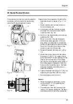
Страница 19: ... procedure Max switch on period 120 seconds 4 Release threaded clamping pin 1 Fig 13 5 Adjust the boring range with the adjus ting screw 2 Fig 11 12 using a hexa gon wrench WAF 2 5 and reading off the display at the same time The actually set value for the diameter at the slider or the cutting edge is displayed Note the following No preceding sign diameter increase negative preceding sign diameter...

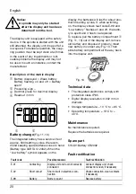
Страница 20: ...ll last for about ano ther 50 setting cycles If when switching on the display shows fault code E 99 and Low battery flashes on and off the batte ry is spent and it has to be replaced To replace pull the battery compartment 5 Fig 11 13 out of the display unit remove old battery and dispose of properly Insert new battery in correct way Fig 13 Then slide battery compartment all the way back into the ...

Страница 21: ...t is available at www tool architect com Your Benefits Find the ideal Wohlhaupter tool combination to meet your requirements Independently select and virtually assemble your boring tool Show the complete boring tool assembly as 3D model Save several configurations Quick and easy to request quotations for the desired composed configurations Tool Architect The Tool Configurator by Wohlhaupter Wohlha...

Страница 22: ...age 27 4 3 Équilibrage 27 5 Maintenance 28 6 Accessoires 28 7 Pièces de rechange 28 3E Affichage digital externe 29 Remplacement de la pile 30 Caractéristiques techniques 30 Maintenance 30 Pièce de rechange 30 Dépannage 30 Les outillages Wohlhaupter sont en développement permanent Les informations les plus récentes sont disponib les à partir de nos catalogues ainsi que sous le site Internet www wo...

Страница 23: ...r le consulter si besoin est 2 Utilisation et production Cet outil est prévu pour l usinage d alésages allant de Ø 0 4 mm à Ø 152 mm Pour chaque plage de diamètres un programme d accessoires complète les besoins des utilisateurs Alésage Pour la plage Ø 0 4 6 5 mm programme mini alésage Pour la plage Ø 6 27 mm porte outils en acier ou carbure Pour la plage Ø 20 53 mm porte plaquettes avec corps cra...

Страница 24: ... le sens axial et se bloquent au moyen d une tige filetée à embout conique 5 au niveau de la face de serrage Tenir compte de la longueur de serrage minimum Température de travail 10 C à 40 C Poids avec MVS 50 28 0 7 kg Vitesses de rotation maximales admis sibles valides pour les accessoires d origine Wohlhaupter correspondants En cas d utilisation du corps ou des guides crantés et des porte plaque...

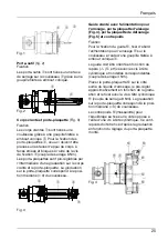
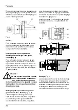
Страница 25: ...age porte plaquette d alésage Fig 4 porte plaquette de détourage Fig 5 et contrepoids Fixation Pour la fixation du guide 0 fixer d abord l alimentation pour l arrosage ß sur le coulisseau à l aide d une goupille filetée à embout conique 5 Le guide doit être orienté en fonction du repère et fixé avec les vis à tête cylindrique et rondelles correspondantes couple de serrage 4 Nm Placer le porte plaq...

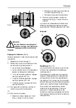
Страница 26: ...ica tion Veiller à la bonne fixation de l alimentation avec la goupille conique filetée sinon il y a risque d accident par défaut de serrage Porte plaquette pour détourage sans guide cranté Ø 4 58 mm Fig 7 8 Tenez compte du montage décalé de 180 pour la fixation des porte plaquettes pour détourage sans guide cranté En cas d utilisation de ces porte plaquettes pour détourage et en raison du montage...

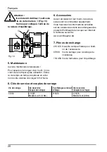
Страница 27: ...en tournant à gauche Fig b Ramener à la position recherchée 3 Serrer la vis de serrage couple de serrage 3 Nm Fig c valeur 20 sur le vernier La course du coulisseau est limitée Une tentative de réglage au delà de la butée peut entraîner l endommagement de l outil 2 0 3 0 1 0 0 40 10 15 5 0 a 2 0 3 0 10 0 4 0 b Beispiel Équilibrage Fig 10 L outil est doté d une rainure pour la mise en place de mass...

Страница 28: ...oires sont à commander séparément Vous trouverez les informations actuelles sur les accessoires dans les catalogues des produits Wohlhaupter ainsi que sur Internet à l adresse suivante www wohlhaupter de 7 Pièces de rechange 215 674 Goupille conique filetée pour fixati on de l accessoire 07033 Vis de serrage pour le serrage du coulisseau 116 353 Vis de fermeture pour l équilibrage Fig 10 1 2 8 Clé...

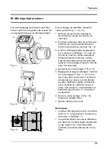
Страница 29: ...de marche maxi 120 secondes 4 Desserrer la vis de serrage 1 Fig 13 5 Réglage de la plage d alésage à l aide de la vis de réglage 2 Fig 11 12 au mo yen d une clé six pans de 2 5 et lecture simultanée sur l écran L écran affiche la valeur réellement réglée au diamètre sur la coulisse ou l arête de coupe À noter pas de signe augmentation du diamètre signe moins diminution du diamètre 6 Serrer la vis ...

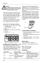
Страница 30: ...équipé d un dispositif de sé curité Au démarrage de la broche l affich eur s il est encore accouplé se détache dès la moindre prise de vitesse Le point de couplage doit être maintenu propre pour garantir un fonctionnement sûr L afficheur ne doit pas être mis en service en cas de dysfonctionnement ou d anom alie Contacter dans ce cas le fabricant Description de l affichage métrique 1 Affichage du n...

Страница 31: ...m Anschluss ein präzises Angebot an Der Tool Architect ist unter www tool architect de erreichbar Ihre Vorteile Die ideale Werkzeugkombination für Ihre Anwendung finden Eigenständig Ihr Werkzeug virtuell konfigurieren und zusammenbauen Das zusammengestellte Komplettwerkzeug als 3D Modell darstellen Verschiedene Konfigurationen speichern Schnell gewünschte Konfigurationen als Angebote anfordern Woh...

Страница 32: ...ur machining specialists are familiar with the conditions and requirements of all industrial branches they will provide you with expert advice to achieve profitable solutions Du premier contact jusqu à la mise en œuvre dans le monde entier les clients font appel à nos outils et à nos services La présence sur site ou l assistance téléphonique de notre service techni que n est que l un des aspects d...

Отзывы: