4. Operation
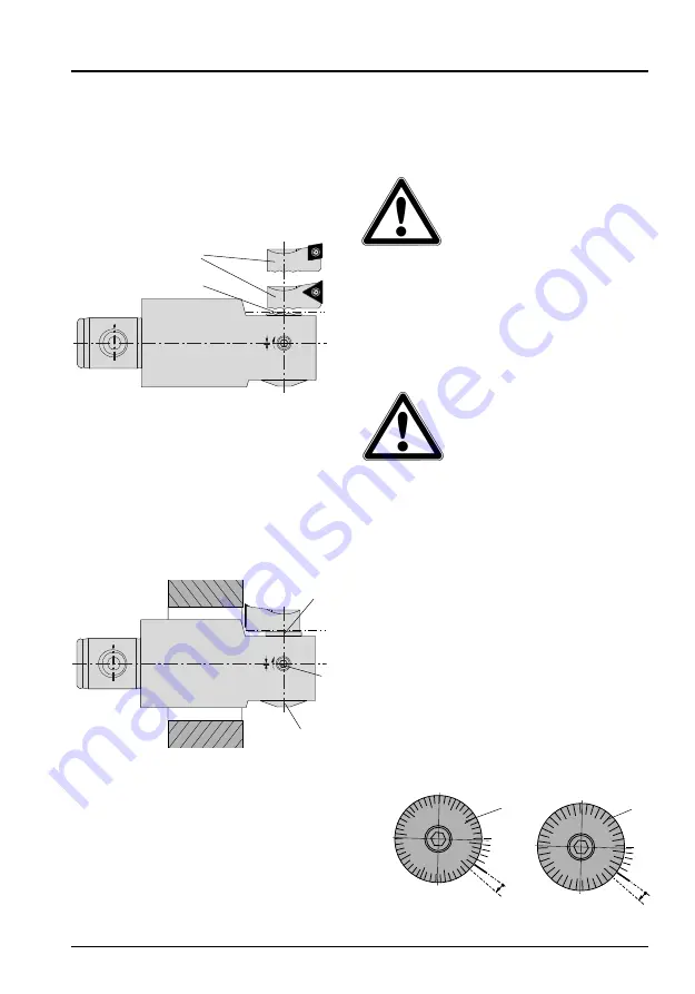
Securing the insert holders
The slider
5
is especially pro filed to
fixed quick and easy different insert hol-
ders
2
(Fig. 3).
Torque for the insert holder screw, see
Technical data page 12.
Reverse machining
(Fig. 4)
For back boring the insert holder is
turned through 180° and mounted on
the slider.
Attention: Back boring then takes
place with the machine spindle
rotating anti-clockwise.
Clamping
(Fig. 4)
To clamp the slider
5
the tool is fitted
with a clamping screw
6
.
When remov ing metal, this clamping
screw
6
must be used to clamp the sli-
der
5
. Before and after each adjustment,
the clamping arrangement must be
operated.
Graduated dial
7
for the adjustment is
located below the tool clamping point.
Only one key is needed to operate both
functions.
To avoid damange to parts of
the adjustment mechanism,
do not make any diameter
adjustments in the
clamped state.
Diameter adjustment
The matt chrome dial
7
gives an exact
reading of the diameter setting. The
distance of the adjustment is limited.
Please follow the sequence of operations
for setting the diameter as set out below.
To avoid damage to parts,
never use force when carry
out adjustment.
Example:
Boring tool 310 004 (320 004)
1. Slacken clamping screw
6
.
2. For the diameter setting, adjust the
tool by turning the dial
7
either
- on a tool setting device or
- by carrying out a trial drilling or
gauge cut on the machine
One revolution of the dial is equivalent
to the slider (and hence also the cut-
ter on the tool) undergoing a diameter
adjustment of 0.5 mm (.025"). One
division on the dial corresponds to a
diameter adjustment of 0.01 mm
(.0005") (Fig. 5).
9
English
Fig. 3
5
2
Fig. 4
5
6
7
20
30
10
0
40
Fig. 5
1
0
15
5
0
metric:
inch:
7
7


