background image

Wogaard Coolant Saver

TM


Manual


Version 1.2-Eng


Page 

2

 of 

19


Preface 

Thank you for purchasing the Wogaard Coolant Saver

TM

. This unit is designed and 

optimized specifically for use with machine tools. It employs Wogaard “patent 

pending” resource-saving technology that saves you money on your coolant and 

cutting oil budget. Using the Wogaard Coolant Saver

TM

 on machine tools equipped 

with chip-conveyors effectively reduces the impact on the environment from general 

machining operations, where coolant or cutting oil is used. 

All components are highly durable and should provide a trouble-free user experience 

for many years. Please read this manual to understand the functions and 

characteristics of the unit and keep it for future reference. 


London, July 2010 


Christian Woergaard 

Managing Director


WOGAARD LTD. 

Содержание Coolant Saver

Страница 1: ...d Instruction manual Wogaard Wogaard Wogaard Wogaard Coolant Saver Coolant Saver Coolant Saver Coolant Saver Instruction manual Coolant Saver Coolant Saver Coolant Saver Coolant SaverTM TM TM TM Versi...

Страница 2: ...tting oil budget Using the Wogaard Coolant SaverTM on machine tools equipped with chip conveyors effectively reduces the impact on the environment from general machining operations where coolant or cu...

Страница 3: ...s Preface 2 Table of contents 3 Safety precautions 4 Introduction 6 General description 6 Main components 7 Setup 8 Tools required for installation 8 Installation 9 Operation 14 Specifications 16 Prod...

Страница 4: ...or The unit collects coolant or cutting oil from a chip container and returns it to the cnc machines main reservoir Using the product for anything other than prescribed in the PRODUCT USE LIMITATION i...

Страница 5: ...the machine operation Warning Do not try to separate the unit from the machine piping during operation if the unit is installed in a cramped space where it may be difficult to move the hand tools free...

Страница 6: ...d on the bottom surface of the chip container and a venturi unit that branches off the pipe supplying coolant or cutting oil to the machine tool The pressure from the machine tools coolant pump create...

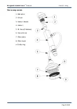
Страница 7: ...Wogaard Coolant SaverTM Manual Version 1 2 Eng Page 7 of 19 Main components 1 Ball valve 2 O Seal 3 Venturi Nozzle 4 Venturi 5 PU hose 3 Metres 6 Vacuum cup 7 Filter plate 8 Filter mesh 9 Circlip ring...

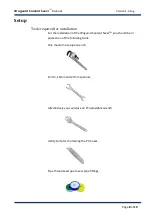
Страница 8: ...n For the installation of the Wogaard Coolant SaverTM you should be in possession of the following tools One medium size pipe wrench 12mm 19mm and 27mm spanner Alternatively you could use an 8 adjusta...

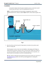
Страница 9: ...the size of the thread on the pipe nipple coming from the coolant pump or filter unit if applicable The thread size is inch or inch on most installations Pipe nipples and T fittings are supplied with...

Страница 10: ...not be started during installation It is recommended to put up a sign that clearly warns not to turn on the pump or machine while the installation is in progress 3 The hose supplying coolant or cuttin...

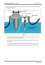
Страница 11: ...ticular example Fig 3 the pipe nipple is screwed into the filter unit and the T fitting is then screwed onto the pipe nipple 5 Screw the venturi unit and ball valve onto the vertical branch of the T f...

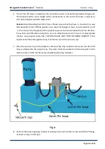
Страница 12: ...he top plate of the coolant reservoir to accommodate the 12mm PU hose If you feel uncomfortable doing this you can alternatively fix the hose in an appropriate manner using regular cable ties THE HOSE...

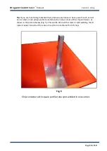
Страница 13: ...such as cast iron or steel it can prove useful to install a tube in one corner of the chip container as shown in the picture below Fig 5 This can be done with screws or spot welding It will make it ea...

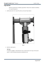
Страница 14: ...d in the previous chapter Installation it is ready for operation 1 Set the ball valve in the shut off position as shown in Fig 6 below Fig 6 2 Start the coolant pump Warning If any leaks breakage or s...

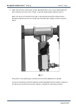
Страница 15: ...um Note The vacuum or collection flow rate is not proportional with the liquid volume flowing through the venturi unit Simply open the ball valve enough to create a vacuum effect Fig 7 The system is n...

Страница 16: ...sible damage or loss Any damages caused by improper packaging are your responsibility Warranty and liability The warranty period is 1 year from the date of delivery During the warranty period the manu...

Страница 17: ...d reseller WOGAARD LTD 823 Salisbury House Email info wogaard com 29 Finsbury Circus Phone 45 2679 1666 London EC2M 5QQ Web www wogaard com Copyright This instruction manual is intended for customers...

Страница 18: ...nozzle 1 3 144 1804 O seal 1 4 144 0404 Ball valve 1 5 144 1604 1 8 pipe nipple for 6mm PU hose 1 6 144 1404 1 2 pipe nipple for 12mm PU hose 1 7 144 0803 6mm PU hose 3 metres 1 8 144 0603 12mm PU ho...

Страница 19: ...ew the venturi unit Once the unit is disconnected from the ball valve you can use a small diameter drill or hex key allen key to pull out the o seal and then the venturi nozzle Remove any chips or deb...

Отзывы: