Wizard MatDesigner 5000 Series Скачать руководство пользователя страница 10

8

Wizard™ International, Inc., 4600 116th St. SW, PO Box 66, Mukilteo, WA  98275   888/855-3335   Fax: 425/551-4350  

wizardint.com

Make sure phone line is plugged into port marked LINE.

Chapter 3: Driver Pak

Driver Pak Replacement

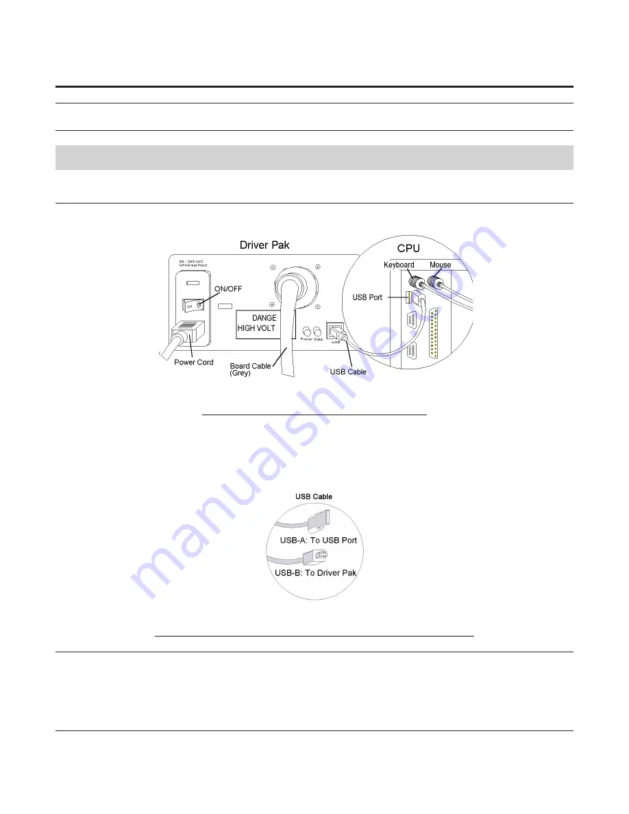
1.  Turn off power to computer.  Follow USB Cable from back of the Driver Pak (shoebox-size peripheral that says Wizard) to 
where it plugs into the USB Port on the back of the CPU (Fig A).  


Fig A.

Fig A: Connection of the Driver Pak to the USB Port

2.  Turn off Driver Pak (flip toggle on back to “

0

”).  Unplug USB Cable from USB Port in back of CPU.  Large grey Board 

Cable is removed by turning black locking ring and pulling gently.  Unplug power cord.

3.  Replace old Driver Pak with new one.  

4. Plug USB Cable (USB-B end) into Driver Pak.   Plug USB Cable (USB-A end) into the USB Port in back of CPU (Fig B).  
Plug Power Cord into Driver Pak.


       Fig B.

Fig B: USB-A plugs into USB Port on CPU.  USB-B plugs into Driver Pak.

WARNING: Be very careful when connecting large gray Board Cable. 
Align four in-line pins carefully before applying pressure to plug them 
in.  If forced in incorrectly, they will bend/break, causing malfunction 
of the Wizard Mat Cutting system.

Содержание MatDesigner 5000 Series

Страница 1: ...5000 HARDWARE GUIDE Revision B Model 5000 MatDesigner...

Страница 2: ...Wizard International Inc 4600 116th St SW PO Box 66 Mukilteo WA 98275 888 855 3335 Fax 425 551 4350 wizardint com NOTES...

Страница 3: ...al Tension 6 Travelling Cable 7 Chapter 2 The CPU 7 Modem Replacement 7 Chapter 3 Driver Pak 8 Driver Pak Replacement 8 No Power Available to the Driver Pak 9 Chapter 4 The Gantry Trolley Plate 10 Gan...

Страница 4: ...djustment 18 V Groove Washer Installation 18 Head Removal 19 Head Installation 20 Check Head Latch Allen Screw 21 Check Plunge Speed 21 Plunge Speed Adjustment 21 Chapter 6 Hardware Maintenance 22 Mai...

Страница 5: ...ment arrives remove the faulty Air Clamp then cut the blue airline and insert a screw into airline and replace Clamp Remaining Air Clamp will hold mat Fig A Fig A Air Clamps are located inside Vertica...

Страница 6: ...hose fitting Lift fitting from its groove and disconnect it by unscrewing the two halves On later machines simply pull the two hoses apart Insert a screw into the airline and replace Clamp This will k...

Страница 7: ...hey are not inflating during the cutting sequence Fig A Fig A Air Clamp test button is located within the left end cap of the Board Gantry Alignment This is located in the Board Section because the Ga...

Страница 8: ...Fig A Fig B Fig C Fig A Line up Gantry to Vertical Clamp to determine which way the top of the Gantry is leaning Fig B Adjusting for leaning to the left Fig C Adjusting for leaning to the right Gantr...

Страница 9: ...ttaches to back of Board below Board Cable Make sure that there is no obstruction to the movement of the Travelling Cable To check move the Gantry Head to the top of the Board then move to the far rig...

Страница 10: ...er Pak flip toggle on back to 0 Unplug USB Cable from USB Port in back of CPU Large grey Board Cable is removed by turning black locking ring and pulling gently Unplug power cord 3 Replace old Driver...

Страница 11: ...end of cable connects to back of the Board in the same manner Fig C Fig D Fig C Board Cable Fig D Back of Driver Pak and back of CPU 8 Turn on CPU Turn on Driver Pak by flipping toggle in back to 1 ma...

Страница 12: ...rizontal Tension for more information because Gantry Horizontal Tension adjustment is located on the Board Gantry Removal 1 Turn off the computer Remove Head See Head Head Removal 2 Remove Wire Carrie...

Страница 13: ...r left edge of the board 7 Remove the Gantry Blocks from the Cable Grabber Arms Cable Grabber Arms and Gantry Blocks are located in the center of crossbar on Gantry one on top and one at the bottom Ea...

Страница 14: ...person holding each end of Gantry carefully align two right Gantry wheels with wheel rails and slide Gantry on until the left wheels just engage the tracks Line up Cable Grabber Arm with side tab slot...

Страница 15: ...e Carrier back into place and replace Allen screws with the long Allen wrench Fig D Fig D Fig D Replace the Allen Screws to the Wire Carrier 5 Reattach small air tube that is connected to a 90 degree...

Страница 16: ...easier to place your hand on the top of the board and hook your thumb underneath the Allen Screw squeeze your hand and thumb together as you tighten the Phillips screws 3 Test again for looseness If...

Страница 17: ...ps screw on top and a pin in the lower axle to turn with your fingers While holding the wrench in one position make a note of the wrench position loosen upper screw by rotating Allen wrench counterclo...

Страница 18: ...tom of the wheel with a 1 2 inch wrench 3 Recheck for tightness and repeat adjustment if necessary Repeat for other wheel Note that wheels can also be set too tight Chapter 5 The Head Changing the Bla...

Страница 19: ...ing the Cut After changing the Blade you will need to close the Head and hit CTRL S to restrt the cut Fig A Fig A Fig A Press CTRL S to continue cutting Measure Blade Depth Checking Blade Depth should...

Страница 20: ...ers with bevel facing you Fig B Push forward on Blade Depth Adjustment Screw HINT Keep a small box of sample pieces of matboard handy to test Blade Depth with each type of matboard before you cut it B...

Страница 21: ...ips screws w star wash ers will make access to the Head Power Plug easier Remove Blade 2 Unplug Head Power Plug by gripping white plug housing firmly not flexible cable and gently rock it back and for...

Страница 22: ...and right Hinge on the Trolley Plate 5 Gently slide Head right rocking up and down may help Head should now slide off Left Hinge pins Fig E Place in a safe place Fig E Fig E Remove Head from pin on le...

Страница 23: ...Fig B Slide Head onto left Hinge Fig C Line up holes on right Hinge Insert Fig D Horizontal Bolt through Head and into right Hinge and back off 1 8th of a turn 6 Connect Head Power Plug and Air Line...

Страница 24: ...very abrasive keeping the Wizard clean is of utmost importance Damage caused by improper maintenance will necessitate return of the Wizard to the factory for rebuilding repair Damage to the Wizard due...

Страница 25: ...nd the wall CAUTION Always wear proper eye protection Offload the Air Regulator Air Regulator can be strapped to left large wall bracket with cable ties provided in Tool Kit hang Air Regulator w glass...

Страница 26: ...t electrical peripherals but it is not a guarantee against all damages in a power surge storm brownout or other mishap For an impending electrical storm unplug phone line from CPU leave the Wizard per...

Отзывы: