background image

\Manuals\GettingStartedManual8500eRev2

10/02/08

1

MatDesigner

 - Getting Started Manual - Model 8500e

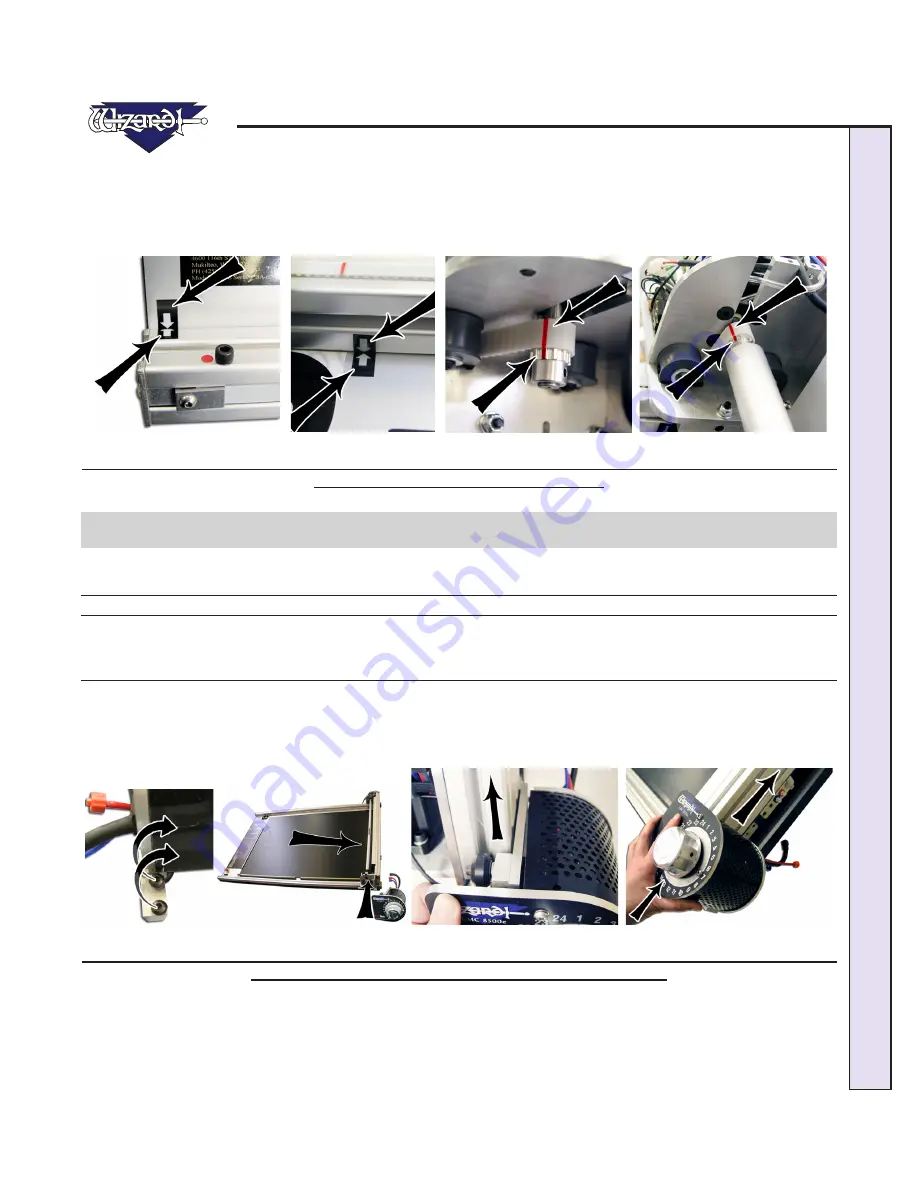
Check the Toothed Belt Lines

Move the Gantry to the right and back.  Looking at the upper Toothed Belt, slowly move the Gantry toward the right again until 

you see a red line on the Toothed Belt.  Confirm that the red line lines up with the red line on the Toothed Pulley (Fig C).  If 

they don’t, call Help Desk.  Without moving the Gantry, look at the lower Toothed Belt and make sure the red lines line up on 

the Toothed Belt and the Toothed Pulley (Fig D).  If not, call Help Desk.


       Fig A.  


           Fig B. 


 Fig C.   


          Fig D.

Fig A: Alignment Arrows on the bottom Rail.  Fig B: Alignment Arrows on the top Rail.  Fig C-D: Make sure the red lines 

line up at the top and the bottom of the Gantry.

Head Installation

Install the Head onto the Gantry

*The Head is shipped with a Blade installed. Take care when handling 
the Head so as to avoid injury.*

1.  Remove the two 5/32" screws from the Head and set aside (Fig A).  Move the Gantry to the right edge of the Board (Fig 

B).  
2.  Point the Head so that the Foot Block faces toward the Board and the wheels are close to the bottom of the Gantry (Fig C).  

Line up the wheels on the Head to the center channels of the Gantry arm.  Ease the Head onto the Gantry (Fig D).


Fig A.    

             Fig B.   

                        Fig C.                                             Fig D.

Fig A: Remove screws from Head.  Fig B: Move the Gantry to the right edge of the Board.  Fig C: Line up Head wheels to 

bottom of Gantry.  Fig D: Ease Head wheels onto Gantry channels.

Содержание 8500e

Страница 1: ...CMC Model 8500e Rev 2 MatDesigner Software Getting Started Manual 8500e with SwitchBlade Technology Revision E MatDesigner...

Страница 2: ...Wizard International Inc 4600 116th St SW PO Box 66 Mukilteo WA 98275 888 855 3335 Fax 425 551 4350 wizardint com NOTES...

Страница 3: ...ping Blocks 10 Unlock the Gantry Wheels 11 Check Squareness 12 Check the Alignment Arrows 12 Check the Toothed Belt Lines 13 Head Installation 13 Install the Head onto the Gantry 13 Expose the Blade 1...

Страница 4: ...otors are Disengaged 27 Align the Head 27 After the CMC Has Cut the Mat 28 If The Cut Doesn t Look Right 28 Changing the Blade 28 Plunge Count 28 Using the 45 Cartridge 29 Changing the Blade 29 Using...

Страница 5: ...eRev2 10 02 08 MatDesigner Getting Started Manual Model 8500e Help Menu 34 Help Screen 35 Contents 35 Index 35 Search 36 Favorites 36 Print 36 Troubleshooting 37 Cuts Look Wavy 37 Blade Keeps Breaking...

Страница 6: ...Wizard International Inc 4600 116th St SW PO Box 66 Mukilteo WA 98275 888 855 3335 Fax 425 551 4350 wizardint com NOTES...

Страница 7: ...ing Started Manual 1 Head Assembly 1 Keyboard 1 Monitor 1 Mouse 1 Power Cord 3 Debossing Kit Tool Kit Allen Wrenches 3 32 7 64 1 8 3 16 5 32 Blade Cartridge 1 If Shipped with a Stand Box 3 4 Stand If...

Страница 8: ...the Stand Wall Mount Assembling the Wall Mount If you purchased a Wall Mount refer to the Wizard CMC Wall Mount Assembly Instructions in the box for assembly instruc tions If the instructions are mis...

Страница 9: ...ght up from the box and remove foam corners Fig C Make sure the Air Lines are not pinched between the Board and the stand 5 Place the foam corners back into the box Save packaging foam corners and Shi...

Страница 10: ...ot remove the black Sintra protective covering Unlocking the Shipping Blocks 1 Locate the four Shipping Blocks holding the Gantry in place There are two on the upper Gantry Fig A One is to the left of...

Страница 11: ...rew from T Nut Fig I A pencil eraser can be useful to remove T Nut from channel Unlock the Gantry Wheels IMPORTANT DO NOT Operate the Wizard without first unlocking the Gantry Wheels 1 The wheels on t...

Страница 12: ...at the top of the Gantry Fig D Remove Allen screw and washer 3 Place the two Allen Screws and the washers you removed into the holes provided on the lower Gantry Plate Fig E These multipurpose Allen...

Страница 13: ...ttom Rail Fig B Alignment Arrows on the top Rail Fig C D Make sure the red lines line up at the top and the bottom of the Gantry Head Installation Install the Head onto the Gantry The Head is shipped...

Страница 14: ...32 screws making sure they go into the Head Grabber Arm and into the Head Fig G then tighten firmly Make sure that the Head and the Head Grabber Arm line up together neatly to ensure correct fitting...

Страница 15: ...s sharp 2 Lift the Head up carefully from the Board as you roll the Gantry to the left so that the Foot Block does not strike the side of the Board Fig C Fig A Fig B Fig C Fig A Locate yellow protecti...

Страница 16: ...lly slide the Trimmer onto the channels on the right side of the Board making sure that the T Nuts slide into the channel of both the upper and lower rails Fig B Move the Straight Line Trimmer to the...

Страница 17: ...try Attaching Air Lines and Air Regulator 1 Go back and make sure that the Air Lines on the back of the Board are not pinched between the Board and the Stand If you have not already done so reattach t...

Страница 18: ...s to the interior of the Stand Arms Fig B Connect Blue Connector on the ST 500 to Blue Air Connector of the Y Connector Connect Red Connector of Gantry to top Red Connector of Y Connector Connect bott...

Страница 19: ...ard Fig A Fig B Fig C Fig A Flip the clamp switch upwards to lock the matboard Fig B Lift handle and raise above mat to trim Fig C Press down on handle and pull downwards Calibration and Alignment of...

Страница 20: ...ng knob by turning it Counter Clockwise 3 Using a 7 16 Open Ended Wrench loosen the Locking Nut see Arrow in Fig B 4 Turn the Alignment Adjustment Screw Clockwise to move the Trimmer to the Right turn...

Страница 21: ...Install upper hood Hook up Computer Hook up Computer Peripherals Hook up the Computer monitor keyboard and mouse by plugging in the color coded plugs into the matching ports on the back of the comput...

Страница 22: ...er end of the Power Cord of the ECU plugs into the back of the Emergency Stop Button in the right hand outlet as viewed from the back Fig D E Make sure that this plug is firmly inserted all of the way...

Страница 23: ...rd Cable was plugged in when we plugged in the Gantry Turn on the System Turn on ECU There is a toggle switch on the back of the ECU 0 is off and 1 is on To turn on ECU by pressing in 1 on the toggle...

Страница 24: ...t New Mat Click Edit New Mat Fig A from the Main Screen Stay on the Single Tab Fig B Note that you have three tabs to select from Single Multi Array Fig A Fig B Fig A Edit New Mat Fig B Single Tab Ope...

Страница 25: ...een Fig D Fig D Enter Border size Outside Size If you had entered your Opening Size and Borders first the program automatically calculates the Outside Size when you tab out of the Borders field Fig E...

Страница 26: ...e New Openings Screen to clear the current numbers if desired Fig A Fig B Fig A Click Cut to go to Cut Preview Fig B The Cut Preview screen Put Matboard on the CMC Makesurethatyouhaveonelayerof dispos...

Страница 27: ...ed if you are able to easily move the Gantry back and forth or move the Head up and down on the Gantry Fig E Fig F Fig E Click Cut to cut the mat Fig F If the motors have been idle it will ask you to...

Страница 28: ...ge Unless the CMC asks you to Align the Head do NOT turn the Foot Block Remove the matboard from the CMC You have cut your first mat Click Back to return to the New Openings Screen If The Cut Doesn t...

Страница 29: ...u lower it Make sure that the base of the Blade is even with the back of the Blade Cartridge and that the length of the Blade is flush with the cartridge Fig A Fig B Fig A Press Blade Cartridge Releas...

Страница 30: ...ide that the cover rotates away from Rotate the Blade Cover closed Fig C D Fig A Fig B Fig C Fig D Fig A Press Blade Cartridge Release Fig B Rotate the Blade Cover open Fig C Insert Blade into Cartrid...

Страница 31: ...ens before pulling out the Emergency Stop Button Pull out the Emergency Stop Button You will now need to Close the MatDesigner software and restart it If you want to save the current mat first see Use...

Страница 32: ...ields But let s say that this time we want to make an Oval opening instead of a Rectangle Click on the Template itself under Template Design Fig A The Template Library will appear Fig B Select 102 Ova...

Страница 33: ...er the Horizontal Clamp and the Vertical Clamp of the CMC Fig C Fig D Fig C Cut from Front Back Indicator Fig D Place matboard into the CMC Click Cut Click Cut to cut the mat Fig E Because the motors...

Страница 34: ...and the Editor Tutorial for information on creating Multi mats See Documentation above Website Check out our website at www wizardint com There you can find useful articles manuals and even a Webstor...

Страница 35: ...ntents You can navigate through the help topics manually through the Contents Tab Click on a topic to display the Help information Click to expand a topic Click to collapse it Fig E Fig E The Contents...

Страница 36: ...es Only Fig G Fig G The Search Tab on the Help screen Favorites You can save Topics in the Favorites Tab for future reference With the desired topic displayed select Add at the bottom of the screen in...

Страница 37: ...Head when Motors are Disengaged in this document for more information Q I Click Cut and the Matboard moves around and does not cut correctly How do I fix this A Make sure that your air compressor is t...

Страница 38: ...aging the Board came in A YES for warranty purposes if you ever need to return a part these boxes will be very useful Rental customers are required to keep all packaging to return the machine at the e...

Отзывы: