


Pag. 9
high performances microphone system
Chan-Group
The
cHannel-gRoUP
item enables the user to
edit channel, channel group and frequency of the
selected itemsl. Change, rotating the knob, the
channel or the group of channels and confirm or exit
with the buttons. To edit the frequency of selected
channel, press the middle button and change it with
the knob. Press the knob to move between MHz and
KHz. Confirm or exit with the buttons.
As shown in the above picture, the display area has
3 rows with:
1] Channel number (0 to 60) and
Channel frequency (in 25kHz step)
2] Group number (1 to 40) and group name (8 char.)
3] Group description (30 char.)
The MRK950 has 40 groups of 60 channels each.
Normally this is too much for wireless microphones
applications.
Connecting with computer with WISYCOM MANAG
-
ER software, it is possible to hide single channels
or even complete groups of channels: once hidden
those items are not shown anymore on the channels
or groups selection. To show channels or groups hid-
den use again the WISYCOM MANAGER software.
Using this software it is also possible to lock chan
-
nels or groups. When a channel is locked, it is not
possible to change the frequency from the front
panel of the receiver. Locking a group means that all
channels are locked. When a channel or a group are
locked, at the left of the group name in the Chan-
Group menu will appear a lock icon as shown in the
picture below. When the lock picture is shown, the
central button is not displayed, thus changing fre-
quency is not possible.
Gr. name
The second item on the radio menu is
gRoUP naMe
;
with this function is possible to assign or change a
name to a group of channel. This short name (8 char-
acter) is displayed at the right of the group number
in the main display view. First chose the the group
and then press the knob. You will be able to edit any
character of the group name rotating the knob. Push
the knob to edit the next character. Confirm or exit
with the buttons.
Squelch
The
sQUelcH
function allows to assign a value at
the squelch of the receiver. Rotating the knob it is
possible to change current squelch level from OFF (it
means no audio squelch) to 1mV. Pressing the knob
you could setup the desired level and also config
-
ure you measurement unit between microVolts and
dBµV. At the end confirm or exit with the buttons.
There is also an automatic procedure to set up the
squelch level, it will be discussed later in this docu
-
ment at the
Autoset SQUELCH
item.
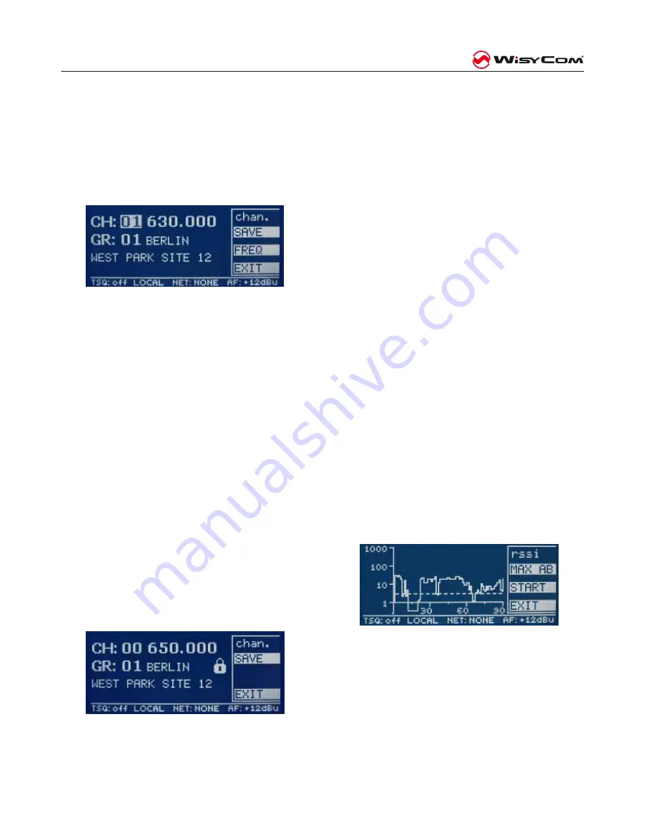
Walk test
The
WalK TesT
function records the RF level of
the two antenna inputs, separately, for a total time
of 90 seconds. Using the first button, it is possible
to choose what to plot: the rf level of the antenna
A or B, the Max value between antenna A and B
or both antenna levels separately. Press START and
walk on your area with a wirelss MIC (transmitting
at the current frequency) while receiver records all
received RF levels. At the end of the sweep time it
is possible to have a look on the graph and check
if there are some “hole of RF signals” and evaluate
your wireless coverage.
Finally push the 3rd button (EXIT) to leave this
fucntion. As “rule of the thumb”, the signal coverage
of the stage could be considered good if, in all the
stage,
the signal “MAX AB” is never lower than
10µV or 20dBµV
. The plot in the picture, shows a
very low coverage with some areas not covered by
the two receiving antennas. In this case probably
the position of the antennas must be changed and/
or the gain of the boosters adjusted.
Содержание MRK 950 EX
Страница 2: ...Pag 2 MRK950 dual true diversity receiver...
Страница 19: ...Pag 19 high performances microphone system...


