background image

Chapter 4: Web Management

EN-68

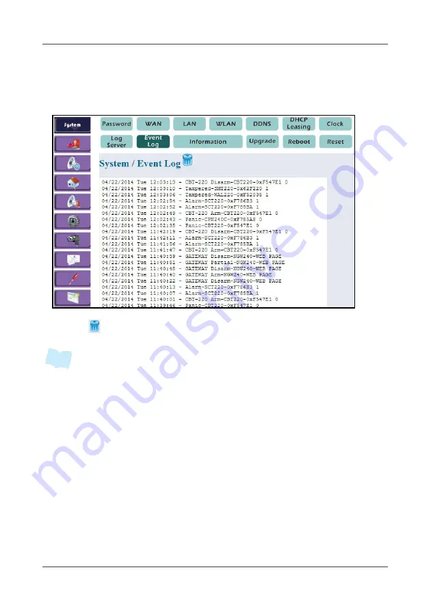
4.1.9 Event Log

This option displays the latest fifty (50) event logs.

1. Select 

System


>


Event Log

.

2. Click 

 to delete all event logs.

All logs are automatically saved into the SD card installed on the Gateway. (50 

logs per file and more than 1,000 logs could be saved).

All logs can also be sent via a designated e-mail. For more information, refer to 

4.8 Notification on page 96.

Alarm, Panic, Tampered, Lost connection, Low battery, Over current protection 

logs will be sent via APP push notification service. For more information, refer to 
3.6 Push Notification Setting (iOS) on page 35 o
r 3.7 Push Notification Setting 
(Android) on page 36.

Note

Содержание la5570

Страница 1: ...Wireless Home Security System User s Manual SENSORS POWER USB SD CARD WAN PAN ALARM SD CARD ...

Страница 2: ...on 8 2 2 Device Joining 12 2 3 Device Deletion 15 2 4 On Site Installation 16 2 5 Surveillance Configuration 29 Chapter 3 APP Management 31 Chapter 4 Web Management 56 4 1 System 56 4 2 Arm Mode 72 4 3 Alarm Delay 73 4 4 Sensor 74 4 5 Siren 85 4 6 Automation 86 4 7 Surveillance 90 4 8 Notification 96 4 9 Security Zone 97 4 10 Logout 98 Chapter 5 Panel Console Management 99 Chapter 6 Appendix 107 6...

Страница 3: ...or relocate the receiving antenna Increase the separation between the equipment and receiver Connect the equipment into an outlet on a circuit different from that to which the receiver is connected Consult the dealer or an experienced radio TV technician for help Caution Any changes or modifications not expressly approved by the party responsible for compliance could void the user s authority to o...

Страница 4: ... expose the device to dripping or splashing Do not place objects filled with liquids such as vases on the device Do not overload the wall sockets extension cords or adapter as this can result fire or electrical shock Disconnect the power plug from the AC outlet if the product is not being used for a long period of time To reduce the risk of fire or electric shock install the device in a temperatur...

Страница 5: ...ncy Alert Easy to trigger panic to alert family by a couple of handheld devices Real Time Event Notification Once any event be detected the system will send out notifications by email or APP push per setup Home Automation Easy to turn ON OFF the home electronic appliances wirelessly to provide a smart living environment 3rd Party Device Integration Easy to integrate with the conventional sensors o...

Страница 6: ... LA5573 Wireless Contact Sensor LA5584 Wireless Pet Immune Motion Sensor LA5582 Wireless Photoelectric Smoke Sensor LA5587 Wireless CO2 Temperature Humidity Sensor Wireless AI Transducer Wireless DI Transducer Wireless Alarm Switch LA5576 Wireless Lock Switch LA5580 Wireless Power Switching AU LA5578 Wireless Relay Switch LA5577 Wireless Power Relay Module LA5575 SENS ORS POW ER USB SD CARD WAN PA...

Страница 7: ...Chapter 1 Introduction EN 7 1 3 System Architecture For details on the installation and configuration about the respective device see Chapter 2 Getting Started on page 8 ...

Страница 8: ... Gateway Accessories 2 1 1 Configuring Gateway Connection 1 Fasten both antennas on the back of the Gateway 2 Adjust the antennas position at 90º angle 3 Plug in the power adapter to the Gateway and the other side to the wall outlet Wireless Gateway Power adapter 2 Detachable antennas Stylus CD SENS ORS POW ER USB SD CARD WAN PAN ALAR M SD CAR D USB USB LAN WAN DC IN 12V WPS SET ...

Страница 9: ...onnection icon Wireless Network Connection Status window will be displayed on the screen LED location Color Indication Power Blue solid Power on USB SD card Orange blinking Normal SD card or USB disk drive is inserted IP camera join When long press the WPS button WAN Blue blinking Communication via Internet service provider via WAN interface PAN Green blinking Sensor network status Alarm Red blink...

Страница 10: ...he default wireless network setting of the gateway SSID TECHview Password none IP address 192 168 19 254 9 Start your web browser It is recommended to use IE7 0 or above 10 Enter the Gateway IP address in the Address field and press Enter 11 Once connected to the Gateway the Login Password window appears Note ...

Страница 11: ...page of Wireless Home Turnkey System WHTS shows up on the screen To change the appropriate settings 4 1 System on page 56 Short press the SET button to join the device Press and hold the SET button for 15 seconds to reset all settings to the factory default settings Unplug the power adapter from the Gateway and plug in again to reboot the system Note ...

Страница 12: ...teway or Router Power Switching With Router it acts as a wireless hub for interconnecting sensors and gateway and it also can expand communication coverage by cascading up to 3 routers RF devices are referring to the Sensors including Console Switch and Transducer 2 2 1 Device Joining via Gateway 1 Plug in the power adapter to the Gateway and the other side to the wall outlet 2 Short press the SET...

Страница 13: ...nsor press both the and buttons until the screen blinks 5 To verify if the device binding process is successful do one of the following Wait for few seconds until both indicators on the Gateway and device turned off Click Refresh icon on the web console to verify if the device binding process is successful 6 Repeat above steps to bind other devices SET Wireless Contact Sensor bracket Wireless Cont...

Страница 14: ...s the SET button at the back of the sensor Wait until the LED indicator blinks green before releasing the SET button For CO2 sensor press both the and buttons until the screen blinks 5 To verify if the device binding process is successful do one of the following Wait for few seconds until both indicators on the router and device turned off Click Refresh icon on the web console to verify if the dev...

Страница 15: ... red and then turns off again indicating the deletion process is complete You can also remove the device binding on the web console However it is only applicable for non battery power device For CO2 sensor press both the button until the screen blinks 2 3 2 Reboot the Gateway Unplug the power adapter from the Gateway and plug in again to reboot the system 2 3 3 Reset the Gateway Press and hold the...

Страница 16: ...he bottom cover firmly The battery is designed for power backup and it will last for 2 hours The tamper proof function will only be activated after the system is armed 2 4 2 Button Console LA5573 a Follow the steps to change the battery Attention CR2032 battery positive side up Note 3V S E T 3V S E T 3V Remove the 4 screws Install the battery Replace the back cover and attach the 4 screws and the ...

Страница 17: ... 2 4 3 Contact Sensor LA5584 a Install the battery into the battery compartment Attention CR2032 battery positive side up b Mount the bracket on the frame side of the door or window and then put the reed on the bracket Button Press Long press 3 seconds FA Full Arm Panic PA Partial Arm On DA Disarm Off FA PA DA 38mm 28mm ...

Страница 18: ... of the reed by less than 10mm distance Then stick on it Due to tamper proof design please make sure the installation is stable to avoid any false alarm 2 4 4 Motion Sensor LA5582 a Mount the bracket on the wall at the height of 1 8 to 2 4 m Do not install it upside down 10mm Close Open Note 1 8 2 4m ...

Страница 19: ... Never face the sensor to the place that pests can climb up directly To save the battery power there is a 30 seconds lock out after motion sensor triggered which means after the motion sensor triggered it will stay in sleep mode for 30 seconds Tamper proof function is only available for Panel Console Contact Sensor Motion Sensor and Siren Alarm switch siren is highly recommended to be joined insta...

Страница 20: ... firmly b Mount the bracket on the ceiling When the sensor detects the smoke it will automatically trigger the alarm and also send out the signal to the Gateway To manually turn off the alarm sound push the button on the front side of the sensor 2 4 6 CO2 Sensor a Hang it on the wall through the rear holds or place it on a stable surface ...

Страница 21: ...ase the setting value 100ppm per time 5 Press the SET button again to access the temperature unit setup 6 Press the or button to switch C or F 7 Press the SET button again to save and exit b Buzzer setup 1 When the buzzer beeps press the ALARM button to stop 2 Long press the ALARM button for 3 seconds to switch ON or OFF the buzzer c Factory default 1 L1 1200ppm 2 L2 2000ppm 3 Temperature unit C 4...

Страница 22: ...wing i Plug in the power adapter to the device and the other side to the wall outlet ii Insert the batteries into the device To insert the batteries refer to the illustration below b Once the alarm is triggered the alarm volume is approximately 90dB To turn off the alarm sound press the upper LED button ...

Страница 23: ...device is power ON the minimum Watt should be powered on for at least 1 hour d Energy Used Cost Input the unit cost at peak time and off peak time by Web Management first and select the accumulate period by month the maximum is 3 months Then the system will automatically calculate the Total Cost Peak Time Cost and Off Peak Time Cost the earliest period is 1 year ago e The power meter value can be ...

Страница 24: ...nnect the GTF200 FL Gas detector as example please see the following diagram e Mount the bracket on the wall f When configuring the detective range the high range value is 20mA and the low range value is 4mA 4 20mA The threshold value will be set based on percentage for example when 20mA setting as 50 4mA setting as 10 if the threshold value setting as 40 that means the device will be triggered wh...

Страница 25: ...3rd party device by DI DO dry contact c The Pin functions are as below Wire 1 Red Dry contact Input Positive Wire 2 White Dry contact Input Negative d To connect the CX 96R CO detector as example please see the following diagram e Mount the bracket on the wall 3V SET Remove the 3 screws Remove the back cover Install the battery Then replace the back cover and attach the 3 screws ...

Страница 26: ...w Wire 1 Red DC 12V Power Input Wire 2 Black Common Wire 3 Yellow Open Collect Digital Output 12V 120mA Max Wire 4 Green Open Close status 0V 12V DC Level input active high Wire 5 White Lock Unlock status 0V 12V DC Level input active high d To connect the SL 130B Electronic lock as example please see the following diagram e Mount the bracket on the wall ...

Страница 27: ...integration and wiring as example SET blinking when joining Reboot blinking when reboot Wire 1 DC 12V Power Input Wire 2 GND Common Wire 3 DI1 Dry contact Input 1 Positive Wire 4 DI2 Dry contact Input 2 Positive Wire 5 DO1 Dry contact Output Wire 6 DO1 Dry contact Output Wire 7 DO2 Dry contact Output Wire 8 DO2 Dry contact Output hard buttons DI DO for trigger simulation NFB No Fuse Breaker ...

Страница 28: ...he wiring pin of 3rd party device by DI DO dry contact c The description of integration and wiring as example Wire 1 AC IN 100VAC 240VAC Wire 2 AC IN 100VAC 240VAC Wire 3 K1 Dry Output 1 Dry contact Wire 4 K1 Dry Output 1 Dry contact Wire 5 K2 Dry Output 2 Dry contact Wire 6 K2 Dry Output 2 Dry contact NFB No Fuse Breaker ...

Страница 29: ... MAC address and configure related IP camera settings refer to 4 7 Surveillance on page 90 3 Reboot both Gateway and IP camera to take effect 2 5 2 Wireless Configuration 1 Connect the Gateway and the IP camera by using an Ethernet cable IP camera will obtain an IP address from the Gateway via DHCP protocol 2 To obtain the IP camera MAC address and configure related IP camera settings refer to 4 7...

Страница 30: ...rotocol 3 To obtain the IP camera MAC address and configure related IP camera settings refer to 4 7 Surveillance on page 90 4 Reboot both Gateway and IP camera to take effect 5 If the WPS pairing process is failed reset the IP camera to its default settings and try it again If the problem persists connect the IP camera to the Gateway either using Wired or Wireless Configuration method The IP defau...

Страница 31: ...interface varies depending on your smart handheld device design 3 1 1 Installing Application iOS Recommended environment iPhone 4 or above iPad2 or above iOS 6 1 or above 1 Download the APP TECHView Home Auto from App Store 2 Install the application 3 1 2 Installing Application Android Recommended environment Android phone CPU 1 GHz or above with Duo core Android 4 0 or above 1 Download the APP TE...

Страница 32: ...hone Wi Fi setting to connect to the gateway s SSID Once connected you may have to enter the encryption key once required Default SSID is TECHview and no encryption key For mobile network user 3G or above skip this network configuration 3 3 Launch APP Touch the APP icon to launch the APP Note ...

Страница 33: ...Password to login You may turn on Remember Password function to retain the password for the next time login The default is 123 same as WebUI 3 5 IP Detection and Selection If Internet link is connected the APP will automatically detect WAN IP To select the detected WAN IP swipe down the screen as shown in the illustration below Note ...

Страница 34: ...r the specific IP Gateway Domain Name directly 3 6 Push Notification Setting iOS When first time login the APP it will automatically register the push notification service and enable the function automatically If you do not want to receive the push notification set the Settings Notifications Center setting to None to disable the function ...

Страница 35: ... Android device a pop up message appears on the screen to confirm if you re allowed to turn on the push notification service Click YES to continue You can also configure the Push Notification at MISC SETTINGS Check to enable Wait for a while to let the system receives the information from the cloud server ...

Страница 36: ...utes even when the APP is off line 3 9 Main Page The current devices status is indicated by its color Red means normal Green means triggered on On iPhone push the Home button to switch to desktop The APP is still running in background Current notification Several notifications unread Options Refresh Function bar Partial Arm Panic Full Arm Disarm Display only at Arm Stay Alarm ...

Страница 37: ...anic Touch and hold the Panic icon shown on the function bar for a few seconds then it will trigger alarm immediately 3 11 Arming Disarming Touch the Arm Stay or OFF icon to arm or disarm the system Main page Full Arm mode Partial Arm mode ...

Страница 38: ...ed in open state 3 13 Alarm Trigger Once any alarm is triggered a pop up message will appear on the screen the system will send out a push message to your smart handheld device and all related device icons will change to Green color to alert If the alarm has been triggered i e 30 minutes ago the related sensor icons remain in Green until the state is changed back click OFF on APP ...

Страница 39: ... the Refresh icon to manually refresh all status immediately The auto refresh timer is approximately 5 15 seconds by default If you quick click the Refresh icon for three times the system will pop up the Prompt window to confirm the connection Refresh ...

Страница 40: ... new name using the on screen keyboard You may also customize the name in any language i e Chinese supported by your smart handheld device 3 16 Device Information Select and touch the device icon once the screen will display the device information which includes device type device ID name zone switch link camera link and its current value ...

Страница 41: ...er Relay Module are DI DO device types Click it to see the setup detail 3 18 Switch On Off For automation type controllers such as Wireless Power Switching or Wireless Lock Switch you can manually turn on off the device switch Relay Switch Relay Switch Power Relay Module ...

Страница 42: ...can be turned ON or OFF randomly by touching the Siren icon 3 19 Current Power Status When power switching is turned on the current measured value will show voltage current power and frequency Touch it to enlarge the display 3 20 On Demand Timer Touch On Demand Timer to select the power on timer Power Off Power On ...

Страница 43: ...utomatically turn the switch on off 3 21 Schedule Setup You can set up to 2 schedules per day Set the desired schedule to ON and touch to access the time and day setup Specify the Start and End time then select the desired day Slide to enable Scroll to select Scroll to select Tick to select ...

Страница 44: ...ulative Usage Touch Usage to select the cumulative period to calculate The total spent energy and cost will be displayed The maximum cumulative period is 3 months and the earliest month shown on the screen is 12 months ago Scroll to select Scroll to select ...

Страница 45: ...era on full screen hold your smart handheld device horizontally for better viewing 3 24 Taking Screenshot For iPhone iPad press both Power and Home buttons to capture a screenshot of the current screen On most Android phones press both Power and Volume Down buttons to capture a screenshot of the current screen Normal view Full screen Full screen ...

Страница 46: ...The device icon will be showed in GREY once disconnected from the Gateway If this happens check if the power supply is unplugged or the battery power is low on each disconnected sensor 3 26 Options Touch Options on the top left to show the sub function page ...

Страница 47: ...You may choose the zone name devices to apply the icon will appear on the screen and enable the specific zone will be armed while Partial Arming To customize the zone name select Other and enter the desired zone name Select link device s Specify zone name Slide to enable Scroll to select location ...

Страница 48: ...ect the switch to link up to 5 switches The icon will appear on the screen By default the switch is set to ON A red power icon at the right bottom indicates the power is on To turn off the switch click the icon The red power icon will disappear To cancel the selection tap the desired switch Touch OK to confirm Linked switches ...

Страница 49: ...ink to configure the camera setup Select the camera first then select the sensor to link The icon will appear on the screen Touch OK to confirm 3 30 System Log Touch Options MISC SETTINGS System Log to view the latest event log stored in the Gateway Linked sensors ...

Страница 50: ... Video Event to view the event trigger video list To play back the video select the desired event and the video playback starts 3 32 Network Information Touch Options MISC SETTINGS Network Information to view the Gateway network information Event trigger video list Full screen ...

Страница 51: ...nging the necessary settings if required The details on how to configure settings on the respective sensor see Chapter 4 Web Management on page 56 3 34 Streaming Channel Touch Options MISC SETTINGS Streaming Channel to select the video streaming setting The default is Video Steam 2 This setting means the lower resolution and suitable for mobile devices ...

Страница 52: ...NGS Login Password to change the password The default password is 123 The password must be at least 3 numeric characters The maximum password length is 12 3 36 Network Settings Touch Options MISC SETTINGS Network Settings to change the WAN mode The default setting is DHCP Note ...

Страница 53: ...e is set to Static IP you have to access the Web Management to change the network setting 3 37 Alarm Delay Touch Options MISC SETTINGS Alarm Delay to configure the delay time The default settings are 10 seconds for outgoing and 30 seconds for incoming PPPoE DHCP Note Drag the bar to select the time Select which devices are on the delay list ...

Страница 54: ...ystem Configure to backup restore the system settings Select Backup Configure to save the current system configuration settings Select Restore Configure to restore the settings that you have saved earlier The Restore Configure function will only available when there is a backup data Note ...

Страница 55: ...Chapter 3 APP Management EN 55 3 39 Logout Touch Options LOGOUT to log out of the APP Then touch Logout to confirm ...

Страница 56: ...TTP web browser In the home page of the WHTS the left navigation bar shows the menu options to configure the system 4 1 1 Password This option allows you to change the login password 1 Select System Password 2 Enter password in the Old Password field The default password is 123 3 Enter the new password in the New Password and Confirm Password fields 4 Click Apply System setting status Menu option ...

Страница 57: ...t service provider you choose you can use one of them to connect to Internet DHCP This option allows the Gateway to obtain an IP address dynamically via DHCP 1 Select System WAN DHCP 2 Click Apply PPPoE This option allows the Gateway to obtain an IP address dynamically via PPPoE 1 Select System WAN PPPOE 2 Enter the user name and password of PPPoE 3 Click Apply ...

Страница 58: ...ic IP This option allows you to configure the Gateway WAN interface using a fixed IP address 1 Select System WAN Static IP 2 Enter the information for IP Address Subnet Mask Default Gateway IP and DNS IP Address as assigned 3 Click Apply ...

Страница 59: ...1 Select System LAN 2 Enter IP Address and Subnet Mask as your preferred The default IP address is 192 168 19 254 3 Click Apply Here below is the default fixed assignment for the last field of IP address i e xx xx xx 60 a 60 99 is reserved for IP camera use b 100 253 is reserved for DHCP client use Note ...

Страница 60: ...nter SSID The default SSID for the Gateway is TECHview 4 On Channel specify the wireless channel To avoid conflicting with other access points set the setting to Auto 5 On Wireless LAN Security select the desired security settings 6 To enable WEP WPA encryption enter the key for data encryption in Auth Mode 7 Click Apply If the WPS function is being used the WLAN security type must be set to WPA N...

Страница 61: ...em DDNS 2 Check Enable to enable DDNS Service 3 Select the DDNS service provider s domain name in the Dyndns System field 4 Enter Username and Password The account information will be provided by DDNS service provider once the DDNS service registration is completed 5 Enter the registered domain name in the Alias field 6 Click Apply ...

Страница 62: ...agement EN 62 Creating a DDNS Domain Name 1 Start your web browser and enter http dyn com dns 2 Select Devices Remote Access 3 Fill in the necessary data and follow the on screen instruction to create a Dyn account Note ...

Страница 63: ...n code will be sent to your e mail account 5 Click PROCEED TO CHECKOUT to continue 6 Fill in the payment information and click PLACE ORDER You will be given a 14 day free trial and you can cancel the application within the trial period The payment will only be charged after the free trial Note Note ...

Страница 64: ...and click Activate Enter a hostname and IP address and select a DDNS server After all settings are complete the DDNS alias will be the combination of hostname and DDNS server For example Hostname xxx DDNS server dyndns web com DDNS alias xxx dyndns web com ...

Страница 65: ...the Gateway DHCP client information The first IP address shown on the above illustration as Always belongs to an IP camera To configure IP camera setup refer to 4 7 Surveillance on page 90 for details 4 1 7 Clock This option allows you to adjust the current system date and time 1 Select System Clock 2 Enter the new Date and Time as required 3 Click Apply Note ...

Страница 66: ...og server information There are two available options Syslog and SIA Select System Log Server Syslog This option allows you to configure the external log server information 1 Select Syslog 2 Enter the gateway ID number and the IP address or Domain name of the external event log server 3 Click Apply ...

Страница 67: ...nt EN 67 SIA This option allows you to configure the external SIA server information 1 Select SIA 2 Enter the IP address or Domain name SIA port number Account number and prefix and specify the receiver number 3 Click Apply ...

Страница 68: ...ateway 50 logs per file and more than 1 000 logs could be saved All logs can also be sent via a designated e mail For more information refer to 4 8 Notification on page 96 Alarm Panic Tampered Lost connection Low battery Over current protection logs will be sent via APP push notification service For more information refer to 3 6 Push Notification Setting iOS on page 35 or 3 7 Push Notification Set...

Страница 69: ...version network and SSID Select System Information 4 1 11 Upgrade This option allows you to upgrade the Gateway software a Upgrade by USB pen drive 1 Select System Upgrade 2 Save the image file whss pck into the USB drive 3 Plug the USB drive into the Gateway USB port 4 Enter the password 5 Click Upgrade ...

Страница 70: ...ect to confirm the selection 4 Click Upgrade to update the firmware For the password information please contact the authorized partners 4 1 12 Reboot This option allows you to power reboot the system once you changed any system settings 1 Select System Reboot 2 To reboot the system click Reboot 3 A pop out message Do you really want to reboot the System to re confirm again Select Yes to proceed No...

Страница 71: ...1 13 Reset This option allows you to reset all settings to the factory default 1 Select System Reset 2 To reset the system click Reset 3 A pop out message Do you really want to reset the system to re confirm again Select Yes to proceed ...

Страница 72: ...ssful See 2 2 Device Joining on page 12 2 Select Arm Mode 3 Select the desired alarm mode Disarm Partial Arm Full Arm Disarm Disarm for the security function only start the disaster prevention function Full Arm Start all disaster prevention and security functions Partial Arm Start partial of the security function and all disaster prevention function ...

Страница 73: ...igure the outgoing incoming alarm delay time once the sensor triggered 1 Select Arm Delay 2 Set the delay time to activate the alarm mode 3 Select the desired sensor on Sensor Delay List This option is only applicable for Contact sensor or Pet Immune Motion sensor 4 Click Apply ...

Страница 74: ... Immune Motion Sensor Wireless Photoelectric Smoke Sensor Wireless CO2 Sensor Wireless AI Transducer Wireless DI Transducer and Wireless Relay DI 1 Be sure to complete all device binding configurations first See 2 2 Device Joining on page 12 2 Select Sensor 3 Click the desired device icon to enter the relevant setup page The console will be automatically refreshed in every 10 seconds Sensor status...

Страница 75: ...nd minimum MIN threshold values You may swap temperature unit ºC or ºF once required 4 Check Enable to enable siren alarm once the current temperature or humidity hits the threshold 5 To bind multiple links with the automation type controllers such as Wireless Power Switching or Wireless Lock Switch select the controller ID in the Switch link field and click Add Select ON or OFF the device when th...

Страница 76: ...ct the controller ID in the Switch link field and click Add Select ON or OFF the device when the alarm is triggered 5 In the Switch link field click Remove to delete the current binded automation type device 6 Click Apply to save the settings You may press the respective button FA PA DA to change the alarm mode While in emergency press and hold FA button to trigger the emergency alert When using t...

Страница 77: ...rity zone while enabling partial arm 4 In Camera Link field select the camera for enabling the event triggered recording 5 To bind multiple links with the automation type controllers to enable remote automatic control select the controller ID in the Switch link field and click Add Select ON or OFF the device when the alarm is triggered 6 In the Switch link field click Remove to delete the current ...

Страница 78: ...le enabling partial arm 4 In the Camera Link field select the camera for enabling the event triggered recording 5 In the PIR Alarm Timer field set the alarm timer for siren once triggered This is to avoid any false alarm likes animal immunity 6 Click Apply to save the settings To avoid false alarm and save the battery power there is a 30 seconds lock out after motion sensor triggered which means a...

Страница 79: ...ore options 3 Select the security zone while enabling partial arm 4 To bind multiple links with the automation type controllers such as Wireless Power switching or Wireless Lock switch select the controller ID in the Switch link field and click Add Select ON or OFF the device when the alarm is triggered 5 In the Switch link field click Remove to delete the current binded automation type device 6 C...

Страница 80: ... Select the security zone while enabling partial arm The current carbon dioxide temperature and humidity readings are displayed in the Value field 4 Set the high range low range threshold values in the its respective field 5 Check Enable to enable siren alarm once the current carbon dioxide reading hits the threshold 6 To bind multiple links with the automation type controllers to enable remote au...

Страница 81: ...option allows you to configure the Wireless AI Transducer settings 1 Click 2 Select the location device number and specify the sensor name Click on the pull down menu to see more options 3 Select the security zone while enabling partial arm The current data reading are displayed in the Value field 4 Set the maximum and minimum metric of the attached third party sensor in the High Low range value f...

Страница 82: ... the current binded automation type device 9 Click Apply to save the settings 4 4 8 DI Transducer This option allows you to configure the Wireless DI Transducer settings 1 Click 2 Select the location device number and specify the sensor name Click on the pull down menu to see more options 3 Select the security zone while enabling partial arm 4 In the Camera Link field select the camera for enablin...

Страница 83: ... when the alarm is triggered 7 In the Switch link field click Remove to delete the current binded automation type device 8 Click Apply to save the settings 4 4 9 Wireless Relay DI This option allows you to configure the Wireless Relay DI settings 1 Click 2 Select the location device number and specify the sensor name Click on the pull down menu to see more options 3 Select the security zone while ...

Страница 84: ...alarm all the time 5 To bind multiple links with the automation type controllers to enable remote automatic control select the controller ID in the Switch link field and click Add Select ON or OFF the device when the alarm is triggered 6 In the Switch link field click Remove to delete the current binded automation type device 7 Click Apply to save the settings ...

Страница 85: ...evice status to turn on off the siren manually 4 Click 5 Select the location device number and specify the sensor name Click on the pull down menu to see more options 6 Click Apply to save the settings If any of the sensor battery is low 2 7V or below the system will automatic generate battery low event log to alert and also trigger the siren alarm for 3 seconds Alarm is activated Alarm is trigger...

Страница 86: ...elay DO 1 Be sure to complete the automation type controller configurations See 2 2 Device Joining on page 12 2 Select Automation 3 You can click device status to turn on off the automation device manually 4 6 1 Remote Power Meter Switch This option allows you to configure the Wireless Power Meter Switch settings 1 Click 2 Select the location device number and specify the sensor name On status Off...

Страница 87: ...ce ii Specify the peak hour time duration iii Select the calculation period The calculation period is from 1 to 3 months The current measure value is displayed in the Power Value field The total energy consumption and cost are displayed in the Total energy used and Total amount fields 4 Click Apply to save the settings By this automation feature you may power control your in house lighting or devi...

Страница 88: ...tion 3 Choose the day s that you want to set Check the respective box 4 Set the Start and End time 5 Click Apply to save the settings If the Schedule 1 and Schedule 2 are overlap the system cannot save the settings 4 6 2 Lock Switch This option allows you to configure the Wireless Lock Switch settings 1 Click 2 Select the location device number and specify the sensor name Click on the pull down me...

Страница 89: ...n page 107 4 6 3 Wireless Relay DO This option allows you to configure the Wireless Relay DO settings 1 Click 2 Select the location device number and specify the sensor name Click on the pull down menu to see more options 3 Set the schedule to automatically switch the device on off in the On Demand Timer field Same as scheduling the Power Meter 4 Click Apply to save the settings Note ...

Страница 90: ...s and view live video via web browser 1 Be sure to complete the IP camera configuration See 2 5 Surveillance Configuration on page 29 2 Select Surveillance 4 7 1 Setup This option allows you to configure the third party IP camera settings 1 Select Camera Setup Click to view in RTSP mode IP camera name Click to view in HTTP mode IP camera MAC address ...

Страница 91: ... on the list Click Renew to renew the list 3 Click the MAC address and it will automatically fill the setup parameters Then confirm the Name IP address and Port mapping information You can also change or add the IP camera parameters manually 4 Click to add the IP camera 5 Reboot both Gateway and IP camera to take effect ...

Страница 92: ...eds Authentication for login IP camera in RTSP mode check enable in the Authentication field and enter the Username and Password 6 Click Apply to save the settings IP camera name IP address of the IP camera Access stream name IP camera RTSP port number Gateway RTSP port number IP camera HTTP port number Gateway HTTP port number Dual stream options Access stream name ...

Страница 93: ...ideo via RTSP mode Click to display video via HTTP mode If you cannot view video in RTSP mode install the VLC software first into your computer To download the VLC software visit http www videolan org vlc The Gateway can only support the video recording up to 4 IP cameras If you using IE 10 browser enable the Display all website in Compatibility View option in Tools Compatibility View Setting Note...

Страница 94: ...Chapter 4 Web Management EN 94 Live view via RTSP mode Live view via HTTP mode ...

Страница 95: ...ack the recorded file 3 Right click on and select Save target as to export the file into your computer The latest 50 events will appears on the Event List and all events are automatically saved into the SD card installed on the Gateway The maximum memory card size is 32 GB If the recorded file is H 264 please rename the file extension name to h264 when you save it to your computer notebook Note ...

Страница 96: ...nable to enable e mail notification service 3 Enter SMTP server s IP address or Domain Name in the SMTP Server field 4 Check Yes to enable SMTP authentication once required 5 Enter username and password in the User name and Password fields once required 6 Enter the e mail address of the recipient in the Email Address field The e mail message can be sent out to up to 3 recipients concurrently 7 Cli...

Страница 97: ...t Other and enter the desired zone name The maximum input data for the customized zone name is 10 characters 4 Check the desired security zone area to enable this zone while partial arming 5 Click Apply to save the settings When you set up the Security Zone Name you can define each sensor s security zone at sensor s setup page Once you check the box of the security zone you can Partial Arm the sel...

Страница 98: ...Chapter 4 Web Management EN 98 4 10 Logout This option allows you to log out of the system Select Logout ...

Страница 99: ...ress the SET button on the gateway for 2 seconds The Alarm LED lights red shortly 2 Press the SET button on the Panel Console The Connect to LA5570 appears on the screen 3 Wait for the date time temperature humidity and system status appear on the Panel Console indicating the binding is completed If the Console Panel displays Connect to LA5570 Fail repeat the above steps until the binding is compl...

Страница 100: ... emergency alarm Press to enter the configuration mode Press again to exit Scroll up or Backspace key Scroll down key Enter key Cancel or Back key Keypad Note LA5572 supports both city power and battery alkaline AA battery x 2 non rechargeable for 2 hours emergency use Once LA5572 is unexpectedly unplugged from the bracket under system arm mode the tam per proof detection will trigger the alarm AW...

Страница 101: ...nsor List Display a list of binding sensors and display the device status Siren Siren List Display a list of binding sirens and display the device status System Password Change the password By default the password is 123 System Clock Adjust the date and time Security Zone Display the available zone list and display the zone status Arm Delay Setup Set the alarm delay time while triggering the selec...

Страница 102: ...activate the alarm Press the or button again to disable the respective arm mode AWAY STAY Press CANCEL key to cancel the setting while counting down Fix the error state on site Set the 0 10 20 30 seconds of the Delay Time in Alarm Delay configuration mode Press ENTER key to bypass AWAY STAY DISARM Password DISARM Password False DISARM OK Enter password to disarm Wrong password please try it again ...

Страница 103: ...mmediately Press and hold the button for 3 seconds To deactivate the alarm Enter the password and press the button 5 6 Using the Function Button Press the to enter the operation mode PANIC PANIC ALARM DISARM Password DISARM OK PANIC is password FUNC FUNC Password Automation Sensor FUNC is password ...

Страница 104: ...hile arming or other device tamper proof i e LA5584 the siren will be triggered automatically Enter the password directly to turn it off c Once the sensor is disconnected from the gateway it will indicate by a strike through as below Check the sensor power status or re join it with the gateway d When the alarm is triggered Panel Console will be sync up and display the alarm message on the screen E...

Страница 105: ...o access or control the specific device The hotkey list as the following Combination keys Device Type C 1 Wireless Temperature Humidity Sensor C 2 Wireless Power Switching C 3 Wireless Lock Switch C 4 Wireless Relay Switch C 5 Wireless Alarm Switch C 6 Wireless CO2 Temperature Humidity Sensor 2 3 1 5 6 4 8 9 7 0 C ...

Страница 106: ...se LA5580 xxxxxx LA5580 Status Open vClose LA5580 Value 220V 1 5A 330W LA5577 xxxxxx LA5577 xxxxxx DI1 LA5577 xxxxxx DI2 LA5577 xxxxxx DO1 LA5577 xxxxxx DO2 LA5577 Status Open vClose LA5575 xxxxxx LA5575 xxxxxx DO1 LA5575 xxxxxx DO2 LA5575 Status Open vClose Sensor LA5573 xxxxxx LA5584 xxxxxx LA5584 Status Open vClose LA5582 xxxxxx LA5587 xxxxxx Siren LA5576 xxxxxx LA5576 Status Open vClose ...

Страница 107: ...ed Contact your installer for detail instructions about the 3rd party sensor installation Sensor type 3rd party sensor Wireless AI Transducer i e 4 20mA CO Detector Gas Detector or Temperature Sensor Wireless DI Transducer i e NC NO CO Detector Smoke Detector Fire Alarm or Gas Detector Wireless Lock Switch Electronic Lock Wireless Relay Switch Wireless Power Relay Module ...

Страница 108: ...er NC Fire Alarm DI Transducer 4 20mA Gas Detector AI Transducer Electronic Lock Lock Controller NC NO Smoke Detector DI Transducer DI Transducer NC NO Gas Detector 1 3 5 7 2 4 6 8 Black AI Transducer F Legend and Description B Negative wiring of detector R Positive wiring of detector G Analog wiring of detector F Fuse DC POWER SUPPLY 24 30 VDC for instrument 4 20mA Current B R G Yellow Red DC12v ...

Страница 109: ... 6 Appendix EN 109 AI Transducer Integration Temperature Sensor DI Transducer Integration CO Sensor Yellow Red Black AI Transducer 4 20mA current power supply 15 40VDC 24VAC 20 1 2 3 4 V GND RH T DC12v Adapter ...

Страница 110: ...Chapter 6 Appendix EN 110 DI Transducer Integration Smoke Sensor Lock Switch Integration ...

Страница 111: ...Chapter 6 Appendix EN 111 Relay Switch LA5577 Power Relay Module LA5575 ...

Страница 112: ... please contact our partner Problem Solutions Cannot access the WHTS web console or APP Check if the AP SSID is correct and it is properly connected to the Gateway The device is disabled while partial arming Make sure this device is not in the selectable security zone Note When the Contact Sensor is not assigned in the security zone it will not arm when partial arming ...

Страница 113: ...connected Re bind this device to re active the connection See 2 2 Device Joining on page 12 The Contact Sensor status is in open mode Place the magnet closer to the Contact Sensor main unit and click Refresh on the web console Problem Solutions ...

Страница 114: ...Arm Set the Contact Sensor to close mode Note When the Contact Sensor is in open mode you cannot enable Partial Arm and Full Arm mode Cannot access the WHTS web console even if the AP SSID is correct Unplug the power adapter from the Gateway and plug in again to reboot the system Problem Solutions ...

Страница 115: ...SET button for 15 seconds to restore the factory default settings Cannot upgrade the Gateway firmware A password is required before updating the firmware Please contact the manufacturer for more information Problem Solutions USB USB LAN WAN DC IN 12V WPS SET ...

Отзывы: