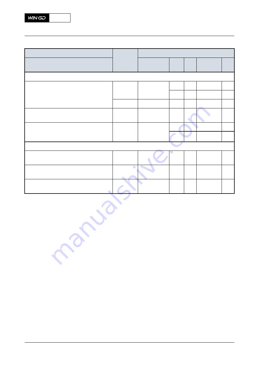
Tab 11-6
Cooling water systems (XX10NN to XX19NN)
Description
Usual oper-
ation (value
or range)
Safeguard setting
Medium / physical value / location
Signal number Func-
tion
Le-
vel
Trigger
value
De-
lay
Cylinder liner, cylinder cover
HT cylinder cooling water / pressure [bar] /
engine inlet connection 02
2.5 to 4
PT1101A
ALM
L
≤
2.0
0
SLD
L
≤
1.8
60
-
PS1101S
SHD
L
≤
1.5
60
HT cylinder cooling water / temperature [°C] /
engine inlet connection 02
72 to 90
TE1111A
ALM
L
≤
70
0
HT cylinder cooling water / temperature [°C] /
outlet each cylinder (engine outlet connec-
tion 03)
TE1121-nnA
ALM
H
≥
95
0
SLD
H
≥
97
60
Scavenge air cooler (SAC)
SAC LT cooling water / pressure [bar] / en-
gine inlet connection 07
2.5 to 4
PT1361A
ALM
L
≤
2.0
0
SAC LT cooling water / temperature [°C] /
engine inlet connection 07
10 to 36
TE1371A
ALM
L
≤
0
SAC LT cooling water / temperature [°C] /
outlet each SAC
10 to 75
TE1381-nnA
ALM
H
≥
80
0
1
This value is applicable for stable operation condition.
2
This value is applicable for transient operation condition.
3
WinGD recommends a setpoint value of 25°C. 36°C is only permitted if the seawater temperature is
32°C.
4
The trigger value should be 21°C if you use the recommended setpoint value of 25°C.
X52
AA00-0000-00AAA-033B-A
Operation Manual
List of usual values and safeguard settings
Winterthur Gas & Diesel Ltd.
- 425 -
Issue 002 2018-11
Содержание X52
Страница 8: ...Page left intentionally blank 8 ...
Страница 113: ...Page left intentionally blank 113 ...
Страница 275: ...7 Installation 7 1 Installation 276 275 ...
Страница 487: ...13 Schematic diagrams 13 1 Schematic diagrams general 488 13 2 List of diagrams 494 487 ...


