


Quick Operation Guide of Digital Video Recorder
8
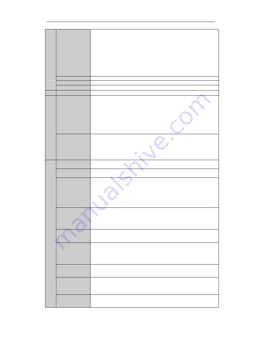
address from 1~254;
Indicator turns red when the SHIFT button is used;
Indicator does not light when the DVR is controlled by a keyboard or by the IR
remote control with the address of 255;
Indicator turns green when the DVR is controlled by IR remote control (with the
address from 1~254) and keyboard at the same time , and the SHIFT button is not
used;
Indicator turns orange : (a) when the DVR is controlled by IR remote control (with
the address from 1~254) and keyboard at the same time and the SHIFT button is used
as well; (b) when the DVR is controlled by IR remote control (with the address from
1~254) and the SHIFT button is used.
ALARM
Alarm indicator turns red when a sensor alarm is detected.
HDD
HDD indicator blinks in red when data is being read from or written to HDD.
Tx/Rx
TX/RX indictor blinks in green when network connection is functioning properly.
5
DVD-ROM
Slot for DVD-ROM.
6
DIRECTION
The DIRECTION buttons are used to navigate between different fields and items in
menus.
In Playback mode, the Up and Down button is used to speed up and slow down
recorded video.
In All-day Playback mode, the Left/Right button can be used to select the recorded
video of next/previous day; in Playback by Normal Video Search, the Left/Right
button can be used to select the next/previous recorded file.
In Live View mode, the directional buttons can be used to cycle through channels.
In PTZ control mode, it can control the movement of the PTZ camera.
ENTER
Confirm selection in any of the menu modes. It can also be used to tick checkbox
fields.
In Playback mode, it can be used to play or pause the video.
In Single-frame Playback mode, pressing the ENTER button will advance the video
by a single frame.
In Auto-switch mode, it can be used to stop /start auto switch.
7
SHIFT
Switch of compound keys between the numeric/letter input and functional control.
1/MENU
Enter numeral “1”;
Access the main menu interface.
2ABC/F1
Enter numeral “2”;
Enter letters “ABC”;
The F1 button can be used to select all items on the list;
In PTZ Control mode, the F1 button can be used to zoom out (zoom-) the PTZ
camera;
In live view or playback mode, the F1 button can be used to switch between main
and spot video output.
3DEF/F2
Enter numeral “3”;
Enter letters “DEF”;
In PTZ Control mode, the F1 button can be used to zoom in (zoom+) the PTZ
camera;
The F2 button can be used to cycle through tab pages.
4GHI/ESC
Enter numeral “4”;
Enter letters “GHI”;
Exit and back to the previous menu.
5JKL/EDIT
Enter numeral “5”;
Enter letters “JKL”;
Delete characters before cursor;
Select the checkbox and ON/OFF switch;
Start/stop record clipping in playback.
6MNO/PLAY
Enter numeral “6”;
Enter letters “MNO”;
In Playback mode, it is used for direct access to playback interface.
7PQRS/REC
Enter numeral “7”;
Enter letters “PQRS”;
Manual record, for direct access to manual record interface; manually enable/disable
record.
8TUV/PTZ
Enter numeral “8”;
Enter letters “TUV”;
Access PTZ control interface.


