


WZDS9100 #2
7
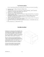
Piping Diagram
1.
Compressor.
2.
Discharge (hot gas) line. The vapor line between the compressor outlet and the condenser coil inlet.
Measure the discharge (hot gas) line temperature here, approximately 12” from the compressor outlet. This
temperature should never exceed 260 degrees.
3.
Receiver. Measure the head pressure at the receiver service valve.
4.
ICM333 Head Pressure Control. See step #10 on page 6.
5.
Liquid line. Measure the liquid line temperature here to determine sub-cooling.
6.
Filter drier.
7.
Sight glass.
8.
Thermostatic expansion valve. See step 12 on page 6.
9.
Suction line. Measure the suction pressure at the compressor suction service valve. Measure the suction
line temperature near the compressor service valve. See step 12 on page 6.
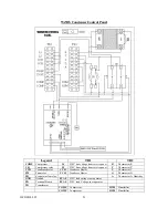
10.
Condenser control panel. Contains the system electrical components.