background image

Cable installation:

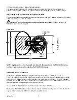
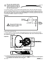
Connect the control cable and power cable to the back of the TRAV’LER Interface box as shown below. 

Note: 

For cable runs longer than 25’ an extension may be purchased. Do not exceed 50’ of cable.

Attach the TRAV’LER control cable to the TRAV’LER Interface Box, as shown in Figure 5A.
Attach the output cable from the Power supply to the TRAV’LER Interface Box. See above. 
Finally, connect a coax cable from the TRAV’LER mount to each of the receivers being used with the TRAV’LER 
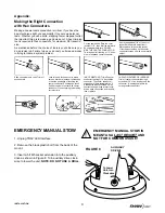
Automatic Satellite Dish. See Appendix for information on properly installing a Hex Connector.

Find a location to plug in the TRAV’LER Power supply and plug it in.

Reflector Installation:

Once the wires are run and the sealant has started to cure:
Check to be sure that there is nothing above the TRAV’LER that might prevent it from raising. You will need at 

least 40” of clearance above the TRAV’LER Mount to ensure that you have room to install the reflector.

Raise Antenna:

There are two ways to raise the antenna. Either Automatic or Manual explained below:

Automatic:

Steps 1-7 explain how to use the TRAV’LER Interface box to raise the mount to install the reflector.

1. Press 

[POWER]

 and hold for 2 seconds to turn “ON” the TRAV’LER Interface Box. Wait until the 

Interface Box finishes “connecting to antenna”. 

* The TRAV’LER  may enter the “Search Routine” after 10 seconds this is normal (See NOTE Below).

2. Press

 [ENTER]

 and hold for 2 seconds or until the unit displays “Enter User Menu”. Press 

[SELECT] 

to move 

the asterisk to “Yes”. Press 

[ENTER]

.

3. Press 

[SELECT]

 to move the asterisk to INSTALLATION.

4. Press 

[ENTER].

 You will be asked to provide a code to enter the Installation Menu.

5.


Press

 [ENTER] 

4 times to enter code 0000.

6.


Press

 [SELECT] 

to move the asterisk to RAISE ANTENNA. Press

 [ENTER]. 

Press 

[SELECT] 

to move the asterisk 

to Yes.

7. Press

 [ENTER]

 the TRAV’LER mount will raise up about half way.

NOTE: 

If the TRAV’LER enters the “Search Routine,” you can still enter the “Menu Mode”. See Steps A & B, p.7.

If the TRAV’LER Mount raises past 1/2 way before RAISE DISH is selected (See Step 6), the TRAV’LER will hit 

its Upper Hard Stop and “Motor Stall” appears. This is Normal.

The “Motor Stall” means the TRAV’LER is all the way up & mount can raise no more. There are two easy ways 

to clear the “Motor Stall”. 

FIGURE 5A

Power

Control Cable

`

`

6


INSTALLATION

Содержание Shaw Direct SK-7002

Страница 1: ... Automatic Multi Satellite TV Antenna Model SK 7002 INSTALLATION MANUAL Winegard Company 3000 Kirkwood St Burlington IA 52601 2000 319 754 0600 FAX 319 754 0787 www winegard com Printed in U S A Winegard Company 2008 2452159 Rev 1 10 WINEGARD SK 7002 ...

Страница 2: ...u begin please make sure you have received all necessary parts to properly install and oper ate your TRAV LER antenna Installation and Operation Manuals Mount Base with 30 Cable Power Control Cable TRAV LER Interface Box Reflector LNBF Feed Arm Packaged separately as the SKA 722 TRAV LER Power supply with 24 AC power cord Gray Coax Cable 30 Black Coax Cable 30 Mounting Hardware bag Cable Entry Har...

Страница 3: ...oof that provides adequate space to allow the TRAV LER antenna to operate The TRAV LER antenna has a Front and Back and must be mounted correctly to avoid dam age to the TRAV LER antenna or the coach The antenna must be mounted 5 degrees of level or the system may require more time to locate the satellite s The Transition plate for the TRAV LER unit is marked FRONT and BACK See Figure 1 FIGURE 1 F...

Страница 4: ...nnect these marks in the shape of the base Replace the TRAV LER antenna base and screw it to the roof Check with your vehicle manufacturer for any special screw requirements before using the supplied screws 3 The unit must be within 5 of level for best operation 4 Make sure that the location offers enough support to attach the TRAV LER antenna securely 5 Find a well ventilated location with a 110 ...

Страница 5: ...ding on the length of the cable on the roof you may need to use cable clamps between the unit and your cable entry plate Clamping every 12 16 should eliminate any unnecessary cable movement FIGURE 4 LIP OF TRANSITION PLATE DO NOT SEAL SEAL WARNING DO NOT cut any wires when you drill the hole for your cables 5 Winegard recommends in stalling the Accessory Detect Cable this can provide an emergency ...

Страница 6: ...utomatic Steps 1 7 explain how to use the TRAV LER Interface box to raise the mount to install the reflector 1 Press POWER and hold for 2 seconds to turn ON the TRAV LER Interface Box Wait until the Interface Box finishes connecting to antenna The TRAV LER may enter the Search Routine after 10 seconds this is normal See NOTE Below 2 Press ENTER and hold for 2 seconds or until the unit displays Ent...

Страница 7: ...ENTER 3 Press SELECT to move the asterisk to INSTALLATION 4 Press ENTER You will be asked to provide a code to enter the Installation Menu 5 Press ENTER 4 times to enter code 0000 6 Press SELECT to move to Calibrate EL 7 Press ENTER 8 Press SELECT to move to YES 9 Press ENTER to start the elevation calibration procedure The LCD should now display Cali brate EL In Progress 10 After a few moments th...

Страница 8: ...g from TRAV LER system Connect the satellite feed to the coaxial input labeled with the symbol of a satellite dish Power on the Shaw Direct receiver and television If your TRAV LER system is properly tuned and receiving signal the satellite dish icon on the front of the Shaw Direct receiver will be highlighted in green If the TRAV LER system is stowed or not tuned to the Shaw Direct satellites the...

Страница 9: ...c object Slide connector onto coax Trim off excess braid Look into end of connector to make sure no braid or aluminum foil touches or has the possibility of touching the center conductor Shorting can result if either comes in contact with center conductor Close crimping tool making correct crimp IN HOT WEATHER Trim off center conductor leaving 3 16 beyond the connector The center conductor expands...

Страница 10: ... before the expiration of the warranty period Winegard Company will at its option either repair or replace the product This Limited Warranty does not apply if the product has been damaged deteriorates malfunctions or fails from im proper installation misuse abuse neglect accident tampering modification of the product as originally manufactured by Winegard in any manner whatsoever removing or defac...

Страница 11: ...11 INSTALLATION ...
Страница 12: ...Winegard Company 3000 Kirkwood St Burlington IA 52601 2000 319 754 0600 FAX 319 754 0787 www winegard com Printed in U S A Winegard Company 2008 2452159 Rev 1 10 ...

Отзывы: