MAINTENANCE
GLIDE 86037550 01/09/07
4-14
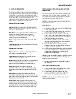
17. SCRUB DECK ACTUATOR
REMOVAL/REPLACEMENT
FOR SAFETY: Before leaving or servicing
machine, stop on a level surface, turn off
machine and set parking brake.
28 IN. & 32 IN.
1. Lower scrub deck, if possible, by pressing one-
touch switch and turn key to off position.
2. Remove lower clevis pin by removing rue ring
from clevis pin, then pull pin out from scrub deck
lift bracket and actuator.
3. Remove upper clevis pin (ball detent type) by
pulling on it’s ring (located on left side), then pull
it out from the frame and actuator. Remove from
the machine, make sure not to allow actuator
barrel position to move.
4. Disconnect actuator from wire harness.
5. Reverse steps to install.
36 IN.
1. Lower scrub deck, if possible, by pressing one
touch switch and turn key to off position.
2. Disassemble actuator from lift brackets on deck
by loosening, but not removing, nuts.
3. Remove upper clevis pin by removing rue ring
from clevis pin, then pull pin out from frame and
actuator.
4. Disconnect actuator from wire harness.
5. Reverse steps to install.
SCRUB DECK ACTUATOR ADJUSTMENT
The actuator will need to be adjusted when replaced.
The actuator needs to be set such that the scrub
deck stops barely touch the rubber bumpers on the
frame in the raised/retracted position.
To adjust the actuator:
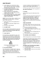
1. While holding actuator barrel to prevent it from
spinning, apply power to the actuator such that it
is fully extended. Positive power to white wire,
and negative/ground to black. Limit switch within
actuator will stop it.
2. Turn barrel out one or more full turns to assure
that when it is retracted it will not bind against
itself.
3. While holding actuator barrel to prevent it from
spinning, apply power to the actuator such that it
is fully retracted. Positive power to black wire,
and negative/ground to white wire. Limit switch
within actuator will stop it.
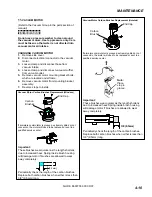
4. With actuator fully retracted, turn barrel in until it
touches the base of the threaded shaft.
5a.
For 28 IN. & 32 IN.
At the bottomed out position, turn the barrel out
3
full turns
, then enough to allow connection to lift
linkage.
5b.
For 36 IN.
At the bottomed out position, turn the barrel out
just enough to allow connection to lift brackets.
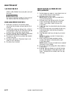
6. Connect actuator to lift linkage and check that in
the raised/retracted position the stops on the
scrub deck barely touch the rubber bumpers on
the frame.
NOTE: If further adjustment is needed, disconnect
the actuator from scrub deck lift linkage and turn the
barrel one half-turn at a time in to make scrub deck
stops closer to bumpers, or out to eliminate
excessive pressure against bumpers.
Содержание 10052480
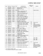
Страница 12: ...CONTROLS GLIDE 86037550 01 09 07 3 5 1 2 3 4 5 6 7 11 14 15 12 21 17 13 20 18 20 19 16 21 10 9 8 ...
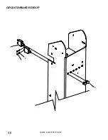
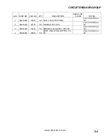
Страница 48: ...CIRCUIT BREAKER GROUP GLIDE 86037550 01 09 07 5 5 1 2 3 4 ...
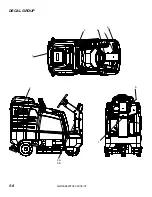
Страница 52: ...DECAL GROUP GLIDE 86037550 01 09 07 5 9 4 2 3 6 1 5A 5B 7 8 9 ...
Страница 54: ...FRONT BUMPER FLOOR GROUP GLIDE 86037550 01 09 07 5 11 1 4 5 6 3 2 3 7 ...
Страница 56: ...FORWARD REVERSE PEDAL GLIDE 86037550 01 09 07 5 13 16 1 13 12 9 8 7 10 2 4 1 1 3 6 5 8 11 16 15 14 13 17 ...
Страница 58: ...SCRUB BRUSH PAD DRIVER GLIDE 86037550 01 0907 5 15 1 6 9 4 8 5 7 2B 2A 2C 3 5 2D 7 5 6 9 4 8 ...
Страница 80: ...SOLUTION DELIVERY GLIDE 86037550 01 09 07 5 37 1 3 4 6 7 10 9 8 2 12 5 14 15 13 11 TO SOLENOID VALVE ...
Страница 88: ...STEERING UPPER GLIDE 86037550 01 09 07 5 45 1 2 3 4 5 6A 6B 8 9 10 7 13 12 16 18 11 14 15 17 ...
Страница 90: ...STEERING LOWER GLIDE 86037550 06 26 12 5 47 8 9 10 12 3 10 9 5 7 8 1 13 17 19 18 20 15 21 6 2 11 4 16 14 ...
Страница 94: ...TANK COVER GLIDE 86037550 01 09 07 5 51 1 2 22 3 21 4 5 20 5 19 6 7 17 16 8 9 12 14 13 7 11 10 15 18 ...
Страница 96: ...VACUUM GROUP GLIDE 86037550 01 09 07 5 53 3 10 1 2 4 5 7 8 6 9 8 11 12 13 ...
Страница 100: ...WHEEL MOTOR SERVICE PARTS GLIDE 86037550 06 25 12 5 57 ...
Страница 110: ...WIRING DRIVE MOTOR GLIDE 86037550 07 05 12 5 67 1 2 ...
Страница 114: ...ACCESSORY PUMP OPTION GLIDE 86037550 01 09 07 5 71 7 5 4 3 10 11 12 2 9 1 2 8 13 14 15 1 16 2 6 15 ...
Страница 116: ...BACK UP ALARM OPTION GLIDE 86037550 01 09 07 5 73 1 5 3 4 2 ...
Страница 118: ...DUAL VACUUM MOTOR OPTION GLIDE 86037550 01 09 07 5 75 7 6 5 4 8 9 1 3 10 11 1 2 12 1 ...
Страница 120: ...WARNING LIGHT OPTION GLIDE 86037550 01 09 07 5 77 1 2 3 4 5 ...
Страница 122: ...GLIDE 86037550 01 09 07 5 79 ...
Страница 123: ...GLIDE 86037550 01 09 07 5 80 ...
Страница 124: ...GLIDE 86037550 01 09 07 5 81 ...

