OPERATION
86373120 FLOOR POLISHER
3-3
CONTROLS
1. Safety Lock –
Prevents unintended operation
of the machine.
2. Switch Levers –
Turns machine on/off.
3. Adjustment
Handle
–
Allows the handle to be
adjusted to a comfortable operating position.
HANDLE HEIGHT ADJUSTMENT
NOTE: The handle is in the up, locked
position from the factory.
The handle adjust bar (1) for the polishers are
individually preset at the factory for optimum
locking efficiency and minimum effort of
engaging. It should not be necessary to adjust
the handle adjust bar unless the handle
adjustment bar (1) the washer (3) and nut (2)
have been disturbed.
NOTE: It is incorrect to make it lock
opposite from the way it was assembled by
applying more force to the nut.
The pivot pin is off center in relationship to the
axis of the handle. To adjust handle, tighten
nut on handle while in the locked position. The
handle is locked when the screw is to the
outside of the machine and the flat on the
opposite side of the handle is flush to the
bracket.
1
2
3
2
1
2
3
4
LOCKING SIDE FLAT
HANDLE
PIVOT PIN
Содержание 1.009-082.0
Страница 16: ...NOTES 86373120 FLOOR POLISHER 3 5 ...
Страница 19: ...NOTES 86373120 FLOOR POLISHER 4 3 ...
Страница 20: ...BRUSH PAD DRIVER 86373120 FLOOR POLISHER 5 1 2A 2K 1 1A 1C 3 3 ...
Страница 22: ...ELECTRICAL 120V 86373120 FLOOR POLISHER 5 3 1 2 6 7 8 9 10 11 5 14 3 13 12 4 10 5 15 16 ...
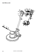
Страница 24: ...ELECTRICAL 230V 86373120 FLOOR POLISHER 5 5 13 12 4 15 10 5 16 17 1 2 6 7 8 9 10 11 5 14 3 ...
Страница 26: ...DECK 86373120 FLOOR POLISHER 5 7 1 2A 2B 3 4 5 6 7 8 10 11 13 14 12 9A 9D ...
Страница 30: ...MOTOR 86373120 FLOOR POLISHER 5 11 10 7 8 9 DUAL SPEED ONLY 2 3 1 5 4 6 11 15 14 13 12 ...
Страница 35: ...86373120 FLOOR POLISHER 5 16 NOTES ...


