5
The cabling is planed together with WindowMaster
®
and with a total bus length as short as possible as well short distance
between the two most remote units connected to the bus. The length and distance specifications must adhere to the above
table. FutureVent
™ bus is a ”free topology” meaning it can be connected as a bus, a star or a combination of the two.
230V supply
The 230V supply cables must comply with current regulations and must not exceed 1.5mm
2
. It is recommended to use many-
core cable e.g. PKAJ (soft).
A Fut
ureVent™ unit has a max consumption of 10W.
It is possible to loop the 230V cables between units.
It is recommended that the 230V supply cables follow the same routing as the FutureVent
™ bus.
If the
FutureVent™ has a cassette of steel, a grounding wire must be clamped to the steel cassette.
Service gateway (used by WindowMaster
®
service engineers)
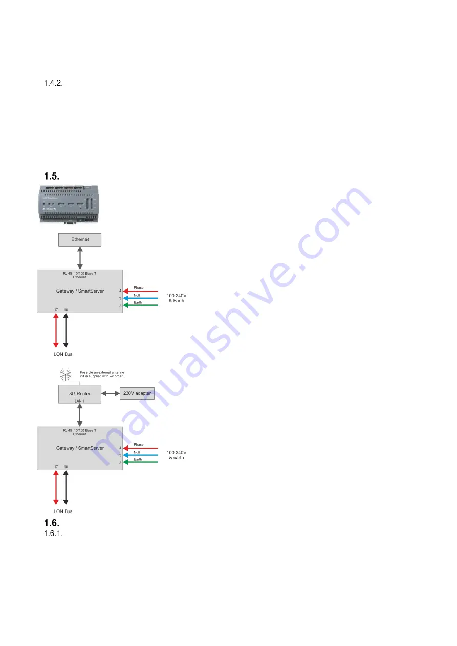
Service gateway:
The SmartServer makes it possible to control the ventilation
system via a PC over the internet as well as perform
maintenance on the installation via remote support.
Install the SmartServer in the control panel and connect the
FutureVent
™ bus to terminal 17 and 18. Additionally supply the
SmartServer with 230V on terminal 3 and 4 and establish an
Ethernet connection.
There are special requirements for the network if the
SmartServer is to be connected to other Ethernet connections.
In case the 3G-router has a built in antenna, place the router
outside the control panel. Additionally, do not place the router
close to metallic surfaces such as water pipes and the like.
If an external antenna is included in the delivery, place the
external antenna outside the control panel
.
Place the antenna on a metallic surface, but not next to other
metallic surfaces such as water pipes and such.
Checking the electrical installation
Checking the functionality of the installation when commissioned.
Switch on the 230V power supply
Just after the power has been switched on, the units will turn to
reset their position. “Clicking” sounds may occur, but
this is normal.
After 1 min, the units will start to run normally, provided the connected control signals and sensor give signals to do so.
Together with a WindowMaster
®
technician, test the installation, by increasing the signal on the analogue input
1.Check if the speed increases.


