background image


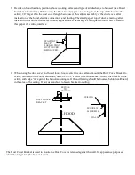
1)  Decide on hood location, position above cooking surface and type of air discharge to be used (See Hood 

Installation Instruction). When using the Duct Cover(s) plan on spacing from the top of the hood to the 

ceiling 1/8” larger than the duct cover length being used. This allows assembly of the duct cover after 

installation of the hood, electric connections and ducting. The small gap, at top of duct, remaining after 
installation will not be noticeable in most applications. If necessary a small quarter-round can be used to 
this gap at the ceiling interface. 


SPACING TO
BE 1/8"
LARGER THAN
DUCT COVER
BEING USED


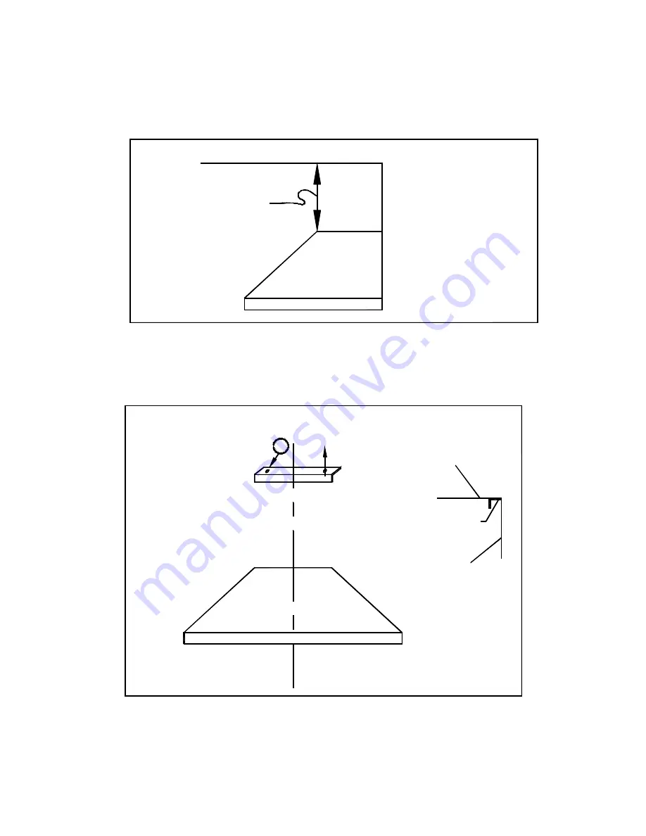
2)  When using the duct cover and hood, locate hood centerline on wall and mount the Duct Cover Bracket to 

ceiling centered on the hood centerline, use #8 x 1-

1/2” screws to mount bracket. Mount the bracket to the 

ceiling with edge “A” against the hood

-mounting wall. Wood framing should be located, behind wallboard, 

in the area of the ceiling. If not, use anchors to fasten bracket to ceiling.  

CL HOOD

BRACKET

DUCT COVER

TO

SECURE

CEILING

#8 SCREWS

SECURE W/2

WALL

CEILING

A


The Duct Cover Bracket is used to ensure the Duct Cover is retained against the wall, for appearance purposes, 
when the longer length of cover is used.


Содержание WPN

Страница 1: ...d Lock Service Disconnecting Means to Prevent Power From Being Switched On Accidentally When The Service Disconnecting Means Cannot be Locked Securely Fasten A Prominent Warning Device Such As A Tag To The Service Panel CAUTION TO REDUCE THE RISK OF FIRE AND TO PROPERLY EXHAUST AIR BE SURE TO DUCT AIR OUTSIDE FOR DUCTED FANS DO NOT VENT EXHAUST AIR INTO SPACE WITHIN WALLS OR CEILING OR INTO ATTICS...

Страница 2: ...rigidize mounting Connect 120 volts 15 amp 60 Hz power supply through the conduit hole in the top of hood connecting to pigtail in hood junction box white to white black to black and connect green ground wire to power supply ground wire per local codes The VEN100E 150E ventilator will require revision of some wiring in the hood receptacle box and possible modification of air discharge opening See ...

Страница 3: ...OF WALL CAP TRANSITION 10100 15 FIG 3 THE 8 DISCHARGE WITH THE TRANSITION 10100 WILL BE ON THE CENTER LINE OF HOOD WIDTH AND ON CENTER LINE OF 12 DIMENSION VERTICAL DISCHARGE FIG 4 14 4 1 8 1 7 5 2 1 4 10 2 1 10 C L HOOD A CUT HOLE IN DRYWALL TO ACCEPT TRANSITION 10100 HORIZONTAL DISCHARGE A CENTER OF ROUND DUCT USING 10100 TRANSITION SECURE TRANSITION TO HOOD USING TWO 6 X 3 8 SHEET METAL SCREWS ...

Страница 4: ...over which can be used as an alternate installation method to enclose the ventilation duct The hood can also be mounted under a cabinet HOOD UNDER CABINET INSTALLATION INSTALLATION HOOD WITH DUCT COVER Two typical installation options shown above When used the duct cover is designed to accommodate typical ceiling heights of 8 ft to 10 ft USING DUCT COVER SECTION 1 2 ONLY SECTION 2 ONLY USING DUCT ...

Страница 5: ...be used to this gap at the ceiling interface SPACING TO BE 1 8 LARGER THAN DUCT COVER BEING USED 2 When using the duct cover and hood locate hood centerline on wall and mount the Duct Cover Bracket to ceiling centered on the hood centerline use 8 x 1 1 2 screws to mount bracket Mount the bracket to the ceiling with edge A against the hood mounting wall Wood framing should be located behind wallboa...

Страница 6: ...ing of hood top to ceiling DESIRED DUCT COVER HEIGHT SCREW BOTH SIDES WITH 8 X 3 8 SCREWS 15 SECTION 19 SECTION 15 SECTION FLANGE 19 SECTION FLANGE 5 Predrive 8x1 2 screws into bottom flange of duct cover Remove screws and aside for use when mounting duct cover to hood 6 Install the duct cover onto the hood flanges facing down and spread the sides of the Duct Cover slightly and position the cover ...

Страница 7: ...4 5 6 18 W 5 1 2 2 1 1 2 3 4 4 3 2 1 RIGHT HEAT LIGHT HEAT LIGHT LEFT LIGHT LEFT RIGHT LIGHT 12 B 1 18 R 22 18 BL 23 18 B 24 18 B 14 18 B 15 18 W 21 18 B 16 18 B 18 18 B 19 18 B 17 18 W 20 18 W 10 18 W 18 B 18 BL 18 R 18 W 25 18 B 12 18 W 13 18 G 11 18 BL 3 18 B 2 18 R 4 BLOWER MOTOR 18 W 26 HEAT LIGHT SWITCH LEFT SWITCH HEAT LIGHT RIGHT BOX RECEPTACLE RECEPTACLE PLUG POWER SUPPLY N G L1 WIRING DI...

Отзывы: