Note: It is recommended to use short wires to hook up this board to the prototype system
for minimal
added noise.
4.1 Adjusting the Amplifier levels for optimal performance
In the handset, application the gain from the handset microphone is set to 27 for the input amplifier. This is
because the acoustical chamber in the telephone type handset lets the electret microphone provide an
output of ~28 mV
RMS
. The chamber typically has a gain of three over a bare microphone (or one placed
with only a small opening to the outside world.) Because of the high sensitivity of the earphone (150
Ώ
impedance) in a typical handset, the output gain from the Power Amp is set to ~0.16 for a satisfactory
listening level.
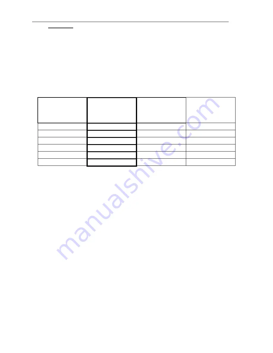
SCHEMATIC
COMPONENT #
TELEPHONE
HANDSET
(Values Populated
on the board)
VoIP PHONE SET
(No acoustic
Chamber)
600
Ώ
LINE IN/OUT
(Tip/Ring)
R3,4 1K 1K 10K
R5,6 27K 91K 10K
C7,8
1200 pF
330 pF
N/U
R9 SELECT
SELECT N/U
R7 20K 20K 27k
R8 3K 3K 27k
Table 4.1: Suggested Components Values By Application
In the VoIP telephone, or small wireless phones, the plastic case is typically too small to provide a
reasonable acoustic chamber. Thus the output from the microphone is less than in the previous example.
This results in having to set the input gain of the CODEC to ~75 to 90. This results in a comparable signal
level to the receive telephone handset but, because of the increased gain, the Signal-to-Noise Ratio (SNR)
has decreased and the signal sounds noisier. On the receive side, the gain is set as in the previous
example. When the Power Amp gain is as low as 0.16 a 32 ohm load can be driven.
If the CODEC is used in a telephone Line Card or a VoIP gateway to the external telephone network then it
will usually be set for 0TLP in and out. This means that the input gain and output gain will be 1:1 and the
values of resistors will be different again. Note that the output of RO- is at 0TLP and going differential will
double this level out of the Power Amp. However, R13 and R14 are 300 ohm resistors to match to the 600
ohm line and the voltage presented to the line will be 0TLP.
Resistor R9 sets the side-tone level (the signal fed back to the ear piece from the microphone so the
telephone sounds “live”) to the level desired by the designer. In most 600 ohm audio line applications, this
feature is not needed. R11 is a just a 0 ohm jumper to allow the board to be used with more than one
model of CODEC. See the chart. R12 is a pull-up resistor for the PCM Transmit line if there is not one
elsewhere in the application.
4


