User’s Manual
WIN Enterprises, Inc.
May, 2009
1
Version 1.0
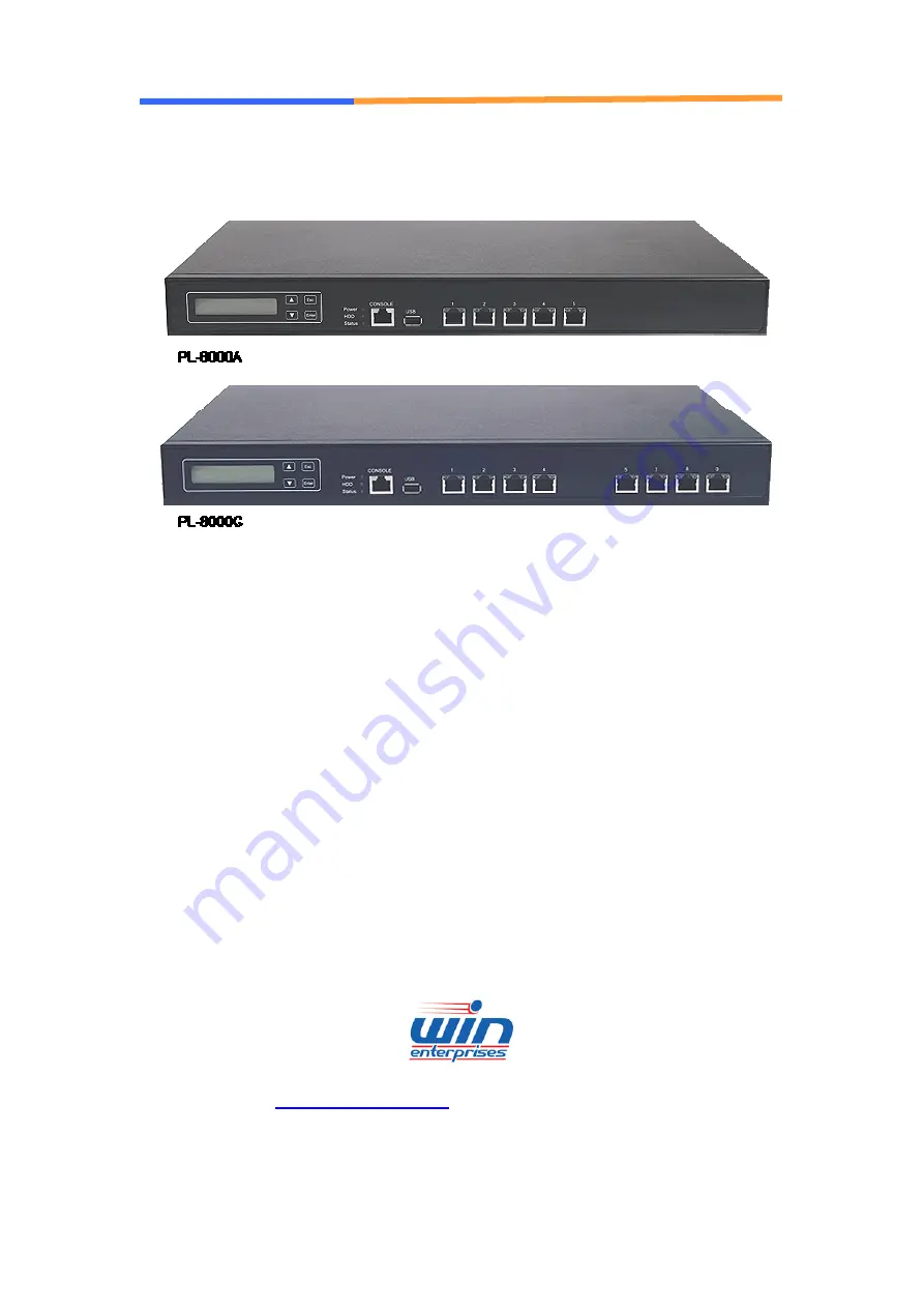
PL-8000
Networking Appliance
1U Rack-mount Intel® EP80579 Network Appliance with 8 x GbE, SATA, CF, LCM
[email protected]
+1 (978) 688-2000
Страница 1: ...er s Manual WIN Enterprises Inc May 2009 1 User s Manual Version 1 0 PL 8000 Networking Appliance 1U Rack mount Intel EP80579 Network Appliance with 8 x GbE SATA CF LCM sales win ent com 1 978 688 200...
Страница 2: ...marks of International business Machine Corporation Award is a trademark of Award Software International Inc Intel is a trademark of Intel RTL is a trademark of Realtek VIA is a trademark of VIA Techn...
Страница 3: ...37A Ethernet module with four GbE Copper 25 3 2 R119 Ethernet module with two GbE Copper and two GbE SFP 26 3 3 R120 Ethernet module with four GbE SFP 27 3 4 R121 Ethernet module with two GbE Copper o...
Страница 4: ...5 2 System Driver Installation 58 5 3 LAN Driver Installation 59 Appendix A Programming the Watchdog Timer 60 Appendix B LAN Bypass Function 63 Appendix C Programming the GPIO 64 Appendix D System Res...
Страница 5: ...ords five GbE Copper and max to 8 GbE Ethernet ports via PCI E by 1 or by 4 on front panel To prevent network problems when the platform shuts down PL 8000 supports one segment of LAN bypass function...
Страница 6: ...Operating Temperature Operating 0 40 C 32 104 F Mechanical and Environment Humidity 10 85 relative humidity non operating non condensing Weight 1pc CTN 5 2kgs 59cm W x 43 2cm D x 15 9cm H Certificatio...
Страница 7: ...Optional 4 CD ROM that contains the following folders 1 Manual 2 System Driver 3 Ethernet Driver 4 Utility Tools If any item of above is missing or damaged please contact your dealer or retailer from...
Страница 8: ...elf before removing any system component from it protective anti static packaging To ground yourself grasp the expansion slot covers or other unpainted parts of the computer chassis Handle the PL 8000...
Страница 9: ...User s Manual WIN Enterprises Inc May 2009 9 1 6 System Layout PL 8000 Front Side PCI E slot Expansion Module optional HDD bay CPU DDR2 SO DIMM Power supply CF card...
Страница 10: ...User s Manual WIN Enterprises Inc May 2009 10 1 7 Board Dimensions...
Страница 11: ...User s Manual WIN Enterprises Inc May 2009 11 Chapter 2 Connector Jumper Configuration 2 1 Connector Jumper Location and Definition...
Страница 12: ...r CN6 SATA0 Connector co layout with CF CN26 USB0 Connector CN7 RESET Pin Header CN27 12V Power jack CN8 GPO Pin Header CN28 PCI Ex4 Gold Finger WIN CN9 4P Power Connector Output CN29 LAN Switch SLOT...
Страница 13: ...2 NC NC BYPASS 3 NC NC 3 3V 4 NC NC GND 5 3 3V 3 3V 3 3V 6 GND GND SATA 7 NC NC SIO GPO7 8 NC NC SIO GPO6 9 3 3V 3 3V SIO GPO5 10 SATA SATA SIO GPO4 11 LAN1_100 GPO19 GPO19 12 LAN1_1G GPO18 GPO18 13...
Страница 14: ...4 LAN4_1G LAN4_ACT LAN4_ACT 25 3 3V LAN5_LNK LAN5_LNK 26 LAN4_ACT LAN5_ACT LAN5_ACT CN 3 4 5 FAN Connector Pin Define 1 Ground 2 12V 3 Speed Detect CN7 Reset Pin Header Pin Define 1 Reset 2 GND CN8 GP...
Страница 15: ...in Assignment 1 12V 2 Ground 3 Ground 4 5V CN11 LPC Connector Pin Define Pin Define 1 3 3V 2 AD 0 3 AD 1 4 AD 2 5 AD 3 6 Frame 7 PCIRST 8 5V 9 CLOCK 10 NC 11 Ground 12 Ground CN12 COM2 Box Header Pin...
Страница 16: ...A9 3 3V B10 3 3V_Stand by A10 3 3V B11 WAKE A11 PE_RESET B12 Power good A12 GND B13 Gnd A13 CLK B14 TXP0 A14 CLK B15 TXN0 A15 GND B16 GND A16 RXP0 B17 5V A17 RXN0 B18 GND A18 GND B19 TXP1 A19 5V B20 T...
Страница 17: ...PS2_GND 9 PS2_VCC 10 PS2_VCC CN15 ATX Power Connector Pin Define Pin Define 11 3 3VSB 1 3 3VSB 12 NC 2 3 3VSB 13 Ground 3 Ground 14 Ground 4 5VSB 15 Ground 5 Ground 16 Ground 6 5VSB 17 Ground 7 Groun...
Страница 18: ...4 PD2 17 SLCTIN 5 PD3 18 Ground 6 PD4 19 Ground 7 PD5 20 Ground 8 PD6 21 Ground 9 PD7 22 Ground 10 ACK 23 Ground 11 BUSY 24 Ground 12 PE 25 Ground 13 SLCT 26 Ground CN18 GPI Pin Header Pin Define 1 G...
Страница 19: ...r Pin Define 1 MDI0 2 MDI0 3 MDI1 4 MDI2 5 MDI2 6 MDI 7 MDI3 8 MDI3 LED D2 Link Activity LED Link Green Activity Blinking D1 Bi Color Speed LED 10 Mbps Off 100 Mbps Yellow 1000Mbps Green CN25 COM1 RJ4...
Страница 20: ...PCI Ex4 Gold Finger WIN Pin Define Pin Define B1 12V A1 GND B2 12V A2 12V B3 12V A3 12V B4 GND A4 GND B5 SMCLK A5 3 3V B6 SMDAT A6 3 3V B7 GND A7 Pull hi to 3 3V B8 3 3V A8 3 3V B9 NC A9 3 3V B10 3 3V...
Страница 21: ...TXN3 A28 GND B29 GND A29 RXP3 B30 USBP0 A30 RXN3 B31 USBN0 A31 GND B32 GND A32 GPIO21 CN29 LAN Switch SLOT Pin Define Pin Define B1 5V A1 GND B2 5V A2 5V B3 5V A3 5V B4 GND A4 GND B5 GND A5 GND B6 GND...
Страница 22: ...P1N 3 USBP1P 4 Ground 5 Ground CN32 ATX SWITCH Pin Define 1 5VSB 2 SIGNAL CN33 LCM Keypad Control Pin Define 1 ACK 2 BUSY 3 PE 4 SLCT 5 Ground CN34 LCM Connector Pin Define Pin Define 1 Ground 2 5V 3...
Страница 23: ...09 23 Jumper Setting JP1 Reset or LAN Bypass with Watchdog Pin Setting 1 2 Reset Default 2 3 Lan Bypass JP3 Clear CMOS Pin Setting 1 2 Hold Data Default 2 3 Clear CMOS JP4 LAN Bypass Pin Setting 1 2 N...
Страница 24: ...g parts Thus it provides users with much greater protection of the data than conventional magnetic disk device Pin Assignment Pin Assignment Pin Assignment Pin Assignment Pin Assignment 1 Ground 11 Gr...
Страница 25: ...ombinations to match various applications and market demand 3 1 R137 Ethernet module with four GbE Copper R137A is a four GbE Copper module The golden edge fingers must be connected with CN13 propriet...
Страница 26: ...r and two GbE SFP R119A is a two GbE Copper and two GbE SFP Ethernet module The golden edge fingers are to be connected with CN13 proprietary connector of PL 8000 board 2 x GbE Copper ports 2 x GbE SF...
Страница 27: ...rnet module with four GbE SFP R120A is a four GbE SFP Ethernet module The golden edge fingers to be connected with CN13 proprietary connector of PL 8000 board 4 x GbE SFP ports Golden Edge Fingers to...
Страница 28: ...nal ODM project The golden edge fingers must be connected with CN13 proprietary connector of CB 7970 board The alternative R121A is a two GbE SFP Ethernet module Picture 1 R121A Picture 2 R121B 2 x Gb...
Страница 29: ...module with four GbE Copper R122A is a four GbE Copper Ethernet module The golden edge fingers to be connected with CN13 proprietary connector of PL 8000 board Golden Edge Fingers to be connected wit...
Страница 30: ...appliance 3 7 R144 Riser card for PCI E x4 add on card standard PCI E x16 connector R144 is one PCI E x4 to PCI E x4 riser card for standard PCI E x4 x1 add on card It must be connected to CN28 PCI E...
Страница 31: ...information for z Date and time z Memory capacity of the appliance z Type of display adapter installed z Number and type of disk drives The CMOS memory is maintained by battery installed on the PL 800...
Страница 32: ...missing z Replace the battery z Change to a different type of CPU z Run the AMI Flash program to update the system BIOS Run the CMOS Setup program after you turn on the system On screen instructions e...
Страница 33: ...ing Discard Changes and Exit ignores your changes and exits the program Pressing ESC anywhere in the program returns you to the main menu 4 3 Menu Options The main menu options of the CMOS Setup progr...
Страница 34: ...vices Use the Advanced Setup option as follows 1 Choose Advanced from the main menu The following screen appears 2 Use the arrow keys to move between fields Modify the selected field using the PgUP Pg...
Страница 35: ...menu shows the CPU related information which is automatically detected by BIOS 4 4 2 IDE Configuration This sub menu allow you to set or change the configurations for the IDE devices installed in the...
Страница 36: ...d Disk Write protect Disabled This menu allows you to enable or disable the hard disk write protect IDE Detect Time Out Sec 35 Selects the time out value for detecting IDE devices Primary IDE Master T...
Страница 37: ...rs one sector at a time PIO Mode Auto Selects the PIO mode for the device DMA Mode Auto Selects the DMA mode for the device S M A R T Auto S M A R T Self Monitoring Analysis and Reporting Technology I...
Страница 38: ...arallel Port Address 378 Selects the Parallel Port base addresses Parallel Port Mode Normal Selects the Parallel Port mode Parallel Port IRQ IRQ7 Selects the Parallel Port IRQ WatchDog Time out Disabl...
Страница 39: ...r s Manual WIN Enterprises Inc May 2009 39 4 4 5 ACPI Configuration This sub menu is used to change the settings for the ACPI General ACPI Configuration This sub menu configures the general ACPI setti...
Страница 40: ...I v1 0 This item allows you to enable or disable RSPD pointers to 64 bit Fixed System Description Tables ACPI APIC support Enabled This item allows you to enable or disable APIC features AMI OEMB tabl...
Страница 41: ...oot Time out 35 This item allows you to select the value for Boot Time out AHCI Port0 Port1 Port2 Port3 Port4 Port5 Sub Menu Not Detected SATA Port0 Auto Select the type of device connected to the sys...
Страница 42: ...gure how the system board responds to a power failure Video Power Down Mode Suspend This item allows you to select the Video power down mode Suspend Standby Hard Disk Power Down Mode Suspend This item...
Страница 43: ...em allows you to enable or disable the PME to generate a wake event Resume On RTC Alarm Disabled This item allows you to enable or disable the RTC to generate a wake event 4 4 8 Clock Generator Config...
Страница 44: ...es Inc May 2009 44 4 4 10 PCI Express Configuration This sub menu allows you to enable or disable the PCI Express link power state 4 4 11 Smbios Configuration This sub menu allows you to enable or dis...
Страница 45: ...s you to select serial port settings Flow Control None This item allows you to select flow control for console redirection Redirection After BIOS POST Always This item allows you to set Redirection co...
Страница 46: ...tem allows you to setup the USB ports Legacy USB Support Enabled Enables support for legacy USB AUTO option disables legacy support if no USB devices are connected USB 2 0 Controller Enabled This item...
Страница 47: ...he PCIPnP Setup option as follows 1 Choose PCIPnP from the main menu The following screen appears 2 Use the arrow keys to move between items and to select values Modify the selected fields using the P...
Страница 48: ...eature When set to Enabled the palette snooping feature informs the PCI devices that an ISA graphics device is installed in the system so that the device can function correctly OffBoard PCI ISA IDE Ca...
Страница 49: ...Move between items and select values by using the arrow keys Modify the selected fields using the PnUP PgDN Keys For information on the various options press F1 key 3 After you have finished with the...
Страница 50: ...Disabed displays normal POST messages AddOn ROM Display Mode Force BIOS Allows you to set the display mode for option ROM Bootup Num Lock On Allows you to select the Power on state for the Num Lock P...
Страница 51: ...us 1st Boot Device SATA PM TRANSCEND This item allows you to set the boot priority Specifies the boot sequence from the available devices A device enclosed in parenthesis has been disabled in the corr...
Страница 52: ...item allows you to set or change the supervisor password The Supervisor Password item on top of the screen shows the default Not Installed After you have set a password this item shows Installed Chan...
Страница 53: ...Chipset from the main menu The following screen appears 2 Move between items and select values by using the arrow keys Modify the selected field the PgUP PgDN keys For information on the various opti...
Страница 54: ...le or disable the AIOC bridge PCI Express Port A0 A1 Enabled This item allows you to enable or disable the PCI Express Port A0 A1 Shared Memory Configuration Shared Memory Configuration Use Default Th...
Страница 55: ...00 Non Coherent Mem Size 00002000 Micro Engine Clock Speed 800 Micro Engine Clock Speed 533 This item allows you to setup the Micro Engine Clock Speed 4 8 2 South Bridge Configuration SMBUS Controller...
Страница 56: ...row keys Modify the selected fields using the PgUP PgDN keys For information on the various options please press F1 key 3 Please press the ESC key to return the main menu after finishing with the Exit...
Страница 57: ...of the parameters on the Setup menus which will provide the best performance settings for your system F9 key can be used for this operation Load Failsafe Defaults This item allows you to load failsafe...
Страница 58: ...an support Windows and Linux operation system as follows Before installation please check your OS version If your OS is not in the following list please upgrade your OS version OS Version DOS DOS 6 22...
Страница 59: ...000 offers the LAN driver in the setup CD Please click the Autorun file and install the driver following the procedures 1 Insert the setup CD of PL 8000 into your CD ROM drive 2 Choose the Drivers fil...
Страница 60: ...er interval to the controller The value range is from 01H to FFH and the related time Watchdog Timer interval is 1 sec to 255 sec Data Timer interval 00 Disabled 01 1 sec 02 2 sec FF 255 sec If you wa...
Страница 61: ...DX 2EH MOV AL 07H OUT DX AL MOV DX 2FH MOV AL 08H OUT DX AL MOV DX 2EH MOV AL 30H OUT DX AL MOV DX 2FH MOV AL 01H OUT DX AL O 2E 07 O 2F 08 O 2E 30 O 2F 01 Program 2 Writing a Watchdog Timer interval...
Страница 62: ...AAH OUT DX AL O 2E F6 O 2F 00 O 2E AA Note This XX value range is from 01H to FFH and the related Watchdog Timer interval is 1 sec to 255 sec as in the previous description Using the Demo Program Upd...
Страница 63: ...dog Timer so that the Watchdog Timer will return to its initial value otherwise your system will set CN20 CN21 LAN ports to bypass state after a time out Note Once the Watchdog Timer time out you need...
Страница 64: ...PI 3 GPI 2 GPI 1 GPI 0 Data Bit 3 Bit 2 Bit 1 Bit 0 0 0 0 0 x0 0 0 0 1 x1 0 0 1 0 x2 0 0 1 1 x3 0 1 0 0 x4 0 1 0 1 x5 0 1 1 0 x6 0 1 1 1 x7 1 0 0 0 x8 1 0 0 1 x9 1 0 1 0 xA 1 0 1 1 xB 1 1 0 0 xC 1 1 0...
Страница 65: ...O 2E 87 O 2E 87 O 2E 29 configuration register CR29 O 2F 01 set GPIO not GAME PORT O 2E 07 point to logical device number reg O 2F 07 select logical device 7 O 2E 30 configuration register CR30 O 2F...
Страница 66: ...cluded in Windows directory to see their map IRQ Assignment IRQ0 Timer IRQ1 Keyboard IRQ2 Interrupt rerouting from IRQ8 through IRQ15 IRQ3 COM2 IRQ4 COM1 IRQ5 PCI device free IRQ6 PCI device free IRQ7...
Страница 67: ...FC00 00000000 00000400 Reserved 00000000 000F0000 00000000 00010000 Reserved 00000000 FEC00000 00000000 01400000 Reserved 00000000 00100000 00000000 07EF0000 Available 00000000 07FF3000 00000000 0000D...
Страница 68: ...Time Clock 81 83 AT DMA controller 87 AT DMA controller 89 8B AT DMA controller 8F 91 AT DMA controller A0 A1 AT interrupt controller C0 DF AT DMA controller F0 FF Math Coprocessor 170 177 IDE Control...
Страница 69: ...ual WIN Enterprises Inc May 2009 69 6000 607F PCI Bus D000 D00E IDE Controller D400 D41E USB Controller D800 D81E USB Controller DC00 DCFE Multimedia Audio E000 E002 Multimedia Audio E400 E402 Multime...
Страница 70: ...net Cat 5 Cable 2M RoHS CB EC5200 00 1 Cross Over 2M Color RoHS CB CO5202 4 00 1 RJ45 to DB9 2M Cable RoHS CB RJDB91 00 1 2m null modem cable RoHS CB DB9200 01 1 VGA CABLE 2mm 15CM RoHS CB IVGA01 00 1...