4
4. Powering up the Wilson U-Booster™ Amplifi er
Make sure the outside antenna cable is connected before
powering up the amplifi er.
Connect the mini-USB plug on the power cable to the U-Boosters
mini USB port located on the bottom of the U-Booster
™
and insert the
adapter into the cigarette lighter outlet of your vehicle.
The U-Booster
™
may remain on all the time. However, leaving the
U-Booster
™
on in a vehicle when it is not running can discharge the
battery in a day or two.
A good option is to power the U-Booster
™
through the ignition switch
so that the amplifi er is turned on and off with the vehicle. The 12 VDC
power source on many vehicles is shut off with the ignition key.
Note: With (optional) charging cables the U-Booster
™
5V power
supply provides charging current to the phone.
IMPORTANT: Do not power up the amplifi er unless the outside
antenna cable is attached to amplifi er.
WARNING:
Use only the supplied Wilson power supply/connector to
power your U-Booster™.
ARNING:
Use only the supplied Wilson po
ower your U-Booster™.
U-Booster™ Power connector.
Connect to Wilson’s power supply
Antenna
connection
n
Phone charging connector port.
Connect to your phone with optional cables
Optional Phone Charging Cables
Understanding the Amplifi er Lights
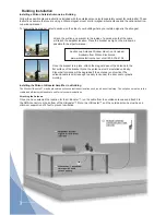
Separation of U-Booster™ and the outside antenna is very important.
In a vehicle, the metal roof acts as a
barrier and helps shield the two antennas from each other, preventing oscillation.
Oscillation can occur when the roof mounted antenna is too close to the U-Booster™ inside the vehicle. An
oscillation (or feedback) in an amplifi er is similar to when a microphone is too close to a speaker in a sound
system, resulting in a loud whistle. An oscillation in a cellular amplifi er, if allowed to occur, can affect nearby cell
sites’ ability to handle calls.
If the light turns red, an oscillation has occured and the amplifi er has powered down to protect the cell tower.
The outside roof mounted antenna needs to be moved farther from the U-Booster™. In a vehicle installation,
move the outside antenna on the roof of the car farther to the rear of the car, but at least 8-12 inches from the
rear or side windows or sunroof. Remove power from the U-Booster™ and reconnect power - this resets the
U-Booster™.
If the light is now green, the oscillation has stopped and the U-Booster™ is working. If the red light is still on,
move the outside antenna farther away and repeat the process.
In a vehicle, always use a magnet-mount or roof-mount antenna. Do not use a glass-mount antenna, as
oscillation may cause continuous shut-down of the U-Booster™.
859967
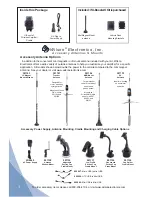
- Micro USB to Mini USB
859968
- HTC USB to Mini USB
859966
- Mini USB to Mini USB


