background image

SIGNALBOOST™ DT Installation Instructions

9

Installing the Amplifi er Unit

Desk or Table Mount

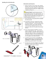
1.  Attach the on-board antenna by screwing it 

onto the threaded connector on the amplifi er.  
Position the antenna vertically by rotating it on 
its base (see Figure 8).  Operating the amplifi er 
with the on-board antenna in a position other 
than vertical will reduce its performance.

2.  Place the amplifi er on a desk, table or similar 

surface where you have routed the coax cable.

3.  Attach the cable to the connector on the 

amplifi er.

Wall Mount

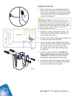
1.  Attach the on-board antenna by screwing it 

onto the threaded connector on the amplifi er 
(see Figure 8).

2.  Position the triangular wall-mount bracket at the 

desired spot on the wall, at least 5 feet up from 
the fl oor and away from any other amplifi er or 
antenna.

3.  Using the bracket as a template, mark the 

locations for the screws using a pencil.

4.  Drill the holes, using a 3/16-inch drill bit, and 

insert the screw anchors.  

Note:

 if you are not 

using the wall-mount hardware in Packet B 
for the cradle antenna, you can use it for the 
amplifi er.  Otherwise, you will need to purchase 
three screws, washers and anchors.

5.  Align the triangular bracket with the screw 

anchors (Figure 9) and attach it with screws 
and washers.  Tighten the screws with a 
Phillips-head screwdriver.

6.  Slide the amplifi er onto the bracket.  Position 

the antenna vertically for best performance 
(see Figure 10).  Operating the amplifi er with 
the on-board antenna in a position other than 
vertical will reduce its performance.

7.  Attach the cable to the connector on the 

amplifi er.

Warning: 

The on-board antenna must have a separation 

distance from all persons that is at least 8 inches.

!

Warning: 

Connecting the amplifi er 

directly to the cell phone with use of an 
adapter will damage the cell phone.

!

Figure 9

Min. 20 feet

Min. 5 feet

Figure 10

Figure 8

Warning: RF Safety: 

The amplifi er must be placed so that 

its on-board antenna has a separation distance of at least 8 
inches from all persons.

!

Warning: 

The amplifi er unit is designed for use in an 

indoor, temperature-controlled environment. It is not intended 
for use in attics or similar locations subject to temperatures in 
excess of 120 degrees Fahrenheit.

!

Warning: RF Safety: 

The amplifi er must be placed so that 

its on-board antenna has a separation distance of at least 8 
inches from all persons.

!
Содержание SignalBoost DT

Страница 1: ...tarted 4 Reasons for Weak Cellular Signals 4 How to Check Your Outside Signal Strength 4 Installing the Cradle Antenna 5 Installing the Amplifier Unit 9 Powering Up the Amplifier 10 Understanding the...

Страница 2: ...apply to any amplifiers determined by Wilson Electronics to have been subjected to misuse abuse neglect or mishandling that alters or damages physical or electronic properties RMA numbers may be obta...

Страница 3: ...f your new amplifier system If you have questions during or after installation please don t hesitate to contact a member of our Technical Support team by phone 866 294 1660 or 435 673 5021 or email te...

Страница 4: ...the SIGNALBOOST DT The signal is then boosted and sent to the on board antenna which communicates with your cell phone or data card When the cell phone or data card transmits the on board antenna pick...

Страница 5: ...walls block the signal Whether you re too far from the nearest cell tower to obtain a usable signal or you re located in an area or building where the signal is obstructed the Wilson SIGNALBOOST DT c...

Страница 6: ...installation of the antenna on a roof or balcony to obtain the strongest signal mounting the cradle outside on a pole not included may be your best option see page 8 IMPORTANT Depending on your partic...

Страница 7: ...e strip and place it on the back of the cradle see Figure 4 Peel the backing from the other side of the strip and press the cradle onto the glass at the desired location 4 Insert the antenna into the...

Страница 8: ...ten the screws with a Phillips head screwdriver 5 Insert the antenna into the cradle with the Wilson label facing in the direction of the cell tower The cable connection should protrude through the bo...

Страница 9: ...ntenna into the cradle with the Wilson label facing in the direction of the cell tower The cable connection should protrude through the bottom of the cradle 5 Connect one end of the supplied coax cabl...

Страница 10: ...fier Otherwise you will need to purchase three screws washers and anchors 5 Align the triangular bracket with the screw anchors Figure 9 and attach it with screws and washers Tighten the screws with a...

Страница 11: ...r pin and then into a wall outlet Understanding the Indicator Light The indicator light on the top of the amplifier will be GREEN when the unit is powered up and working properly If the indicator ligh...

Страница 12: ...ALBOOST DT to get the best coverage You should install the amplifier in the area where you most need an improved signal The farther you are from the amplifier the less improvement you will experience...

Страница 13: ...com About Wilson Electronics Wilson Electronics Inc a leader in the wireless communications industry for over 40 years designs and manufactures amplifiers antennas and related components that signifi...

Страница 14: ...3 7 dBm 4 Power output for multiple received channels downlink Maximum Power The maximum power is reduced by the number of channels Number of channels 800 MHz 1900 MHz 2 13 4 dBm 14 3 dBm 3 9 9 dBm 10...

Отзывы: