Wilden A.025 Original Metal Series Скачать руководство пользователя страница 14

WILDEN PUMP & ENGINEERING CO. 


12 

WIL-10020-E-06


SECTION 8A

MODEL A.025

DIRECTIONS FOR DISASSEMBLY/REASSEMBLY
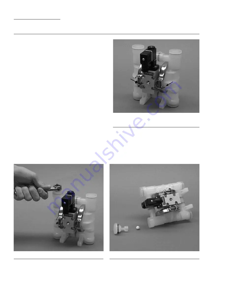
Step 2. 

Figure 2

Using a 1/4" socket wrench, remove the top retainer.

Step 3. 

Figure 3

Inspect the ball retainer, retainer o-ring, and valve ball. Check 
for nicks, gouges, chemical attack or abrasive wear. Replace 
worn parts with genuine Wilden parts for reliable perfor-
mance. Repeat Step 2 for remaining top retainer.

CAUTION:

  Before any maintenance or repair is attempted, the 

compressed air line to the pump should be disconnected and 
all air pressure allowed to bleed from the pump. Disconnect 
all intake, discharge, and air lines. Drain the pump by turning 
it upside down and allowing any fluid to flow into a suitable 
container. Be aware of any hazardous effects of contact with 
your process fluid.

The Wilden model A.025 is an air-operated, double-diaphragm 
pump with all wetted parts of polypropylene or PVDF. The 
single-piece center section, consisting of center block and air 
chambers, is molded from polypropylene. All fasteners and 
hardware are stainless steel. All o-rings used in the pump are 
of special materials and should only be replaced with factory-
supplied parts.

PLEASE read all directions before starting disassembly.

TOOLS REQUIRED:

1/4" Socket Drive 
3/8" Box Wrench
7/16" Wrench
3/16" Rod
Adjustable Wrench
 Vise equipped with soft jaws (such as plywood, plastic
or other suitable material)

NOTE:

 The model used for these instructions incorporates PTFE 

diaphragms and balls. Models with rubber/TPE diaphragms are 
the same except where noted. 

Figure 1

DISASSEMBLY:

Step 1.

Before actual disassembly is started, turn pump upside 
down and drain all liquid trapped in the pump into a suit-
able container. Be sure to use proper caution if liquid is 
corrosive or toxic. Mark each liquid chamber to its respec-
tive air chamber for easy alignment during reassembly.

Содержание A.025 Original Metal Series

Страница 1: ...A 025 WIL 10020 E 06 REPLACES WIL 10020 E 05 S i m p l i f y y o u r p r o c e s s Engin e e ri n g Operati o n Mainte n a n ce Original Series PLASTIC Pumps ...

Страница 2: ...PERATING CONDITION A A 025T PLASTIC Rubber Fitted T series Center Section 8 A A 025T PLASTIC PTFE Fitted T series Center Section 8 B A 025P PLASTIC Rubber Fitted P series Center Section 8 B A 025P PLASTIC PTFE Fitted P series Center Section 8 SECTION 7 INSTALLATION OPERATION A Installation 9 B Operating Principles 10 C Operation and Maintenance 10 D Troubleshooting 11 SECTION 8 DIRECTIONS FOR DISA...

Страница 3: ...henever discharge of static electricity is a hazard CAUTION Do not exceed 8 6 bar 125 psig air supply pressure CAUTION Before any maintenance or repair is attempted the compressed air line to the pump should be disconnected and all air pressure allowed to bleed from pump Disconnect all intake discharge and air lines Drain the pump by turning it upside down and allowing any fluid to flow into a sui...

Страница 4: ...n very aggressive environments Adapter Blocks are available for both the T and P series center sections in all pump sizes See EOM AxB for details Note The x in the above Accu Flo descriptions are used in place of a pump model size See Pump Designation System chart above A 025 ORIGINAL PLASTIC 6 mm 1 4 Pump Maximum Flow Rate 10 6 LPM 2 8 GPM MATERIAL CODES AIR SYSTEM BASE TYPE B ADAPTER BLOCK P PRO...

Страница 5: ...let valve ball and fill the liquid chamber see shaded area FIGURE 2 When the solenoid valve is deenergized the air valve redi rects pressurized air to the back side of diaphragm B The pressurized air forces diaphragm B away from the center section while pulling diaphragm A to the center section Diaphragm B is now on its discharge stroke Diaphragm B forces the inlet valve ball onto its seat due to ...

Страница 6: ...ONAL DRAWING A 025B PLASTIC ACCU FLO T SERIES CENTER SECTION DIMENSIONS ITEM METRIC mm STANDARD inch A 145 5 7 B 25 1 0 C 74 2 9 D 94 3 7 E 140 5 5 F 163 6 4 G 30 1 2 H 30 1 2 J 114 4 5 K 61 2 4 L 74 2 9 M 53 2 1 N 64 2 5 P 5 0 2 3 mm 1 8 BSP FNPT AIR INTAKE 6 mm 1 4 BSP FNPT LIQUID INLET 6 mm 1 4 BSP FNPT AIR EXHAUST 6 mm 1 4 BSP FNPT LIQUID DISCHARGE A A 6 mm 1 4 BSP FNPT AIR INLET 6 mm 1 4 BSP ...

Страница 7: ...L 122 4 8 M 30 1 2 N 132 5 2 P 74 2 9 R 61 2 4 S 53 2 1 T 64 2 5 U 5 0 2 3 mm 1 8 BSP FNPT AIR INLET EXHAUST 6 mm 1 4 BSP FNPT LIQUID DISCHARGE 6 mm 1 4 BSP FNPT LIQUID INLET A 6 mm 1 4 BSP FNPT LIQUID DISCHARGE 6 mm 1 4 BSP FNPT LIQUID INLET 6 mm 1 4 BSP FNPT AIR INLET A B C D E R M L N P F G H J K B C D E G H J K L M N U P R S T F DIMENSIONS ITEM METRIC mm STANDARD inch A 145 5 7 B 25 1 0 C 79 3...

Страница 8: ...formance pumps should be specified so that daily operation parameters will fall in the center of the pump performance curve SECTION 5A PERFORMANCE A 025T PLASTIC PTFE FITTED Height 175 mm 6 9 Width 145 mm 5 7 Depth 107 mm 4 2 Est Ship Weight Polypropylene 1kg 3 lbs Air Inlet 3 mm 1 8 Inlet 6 mm 1 4 Outlet 6 mm 1 4 Suction Lift 4 32 m 14 2 Dry 9 32 m 30 6 Wet Displacement per Stroke 0 017 l 0 005 g...

Страница 9: ...formance pumps should be specified so that daily operation parameters will fall in the center of the pump performance curve SECTION 5D PERFORMANCE A 025P PLASTIC PTFE FITTED Height 180 mm 7 1 Width 145 mm 5 7 Depth 132 mm 5 2 Est Ship Weight Polypropylene 1kg 3 lbs 1 kg PVDF 3 lbs Air Inlet 3 mm 1 8 Inlet 6 mm 1 4 Outlet 6 mm 1 4 Suction Lift 3 96 m 13 0 Dry 9 32 m 30 6 Wet Displacement per Stroke...

Страница 10: ... the stroke rate is modified under static air and fluid pressure condition This curve can be applied to different pressure conditions to estimate the change in flow due to stroke rate These curves demonstrate the flow created when the stroke rate is modified under static air and fluid pressure condition This curve can be applied to different pressure conditions to estimate the change in flow due t...

Страница 11: ... large enough to supply the volume of air necessary to achieve the desired pumping rate Consult manual for performance information The use of an air filter before the pump will ensure that the majority of pipeline contaminants will be eliminated For best results the pump should use an air filter regulator system Sound levels are reduced below OSHA specifications using the standard Wilden muffler 3...

Страница 12: ...ORDS When service is required a record should be made of all necessary repairs and replacements Over a period of time such records can become a valuable tool for predicting and preventing future maintenance problems and unscheduled downtime In addition accurate records make it possible to identify pumps that are poorly suited to their applications PLUMBING CONNECTIONS SECTION 7B OPERATING PRINCIPL...

Страница 13: ... change direction The time required to complete the stroke is determined by a variety of factors which include fluid viscosity and head pressure 3 Check for pump cavitation slow pump speed down to match the thickness of the material being pumped 4 Check for sticking ball check valves If the material being pumped is not compatible with the pump elas tomers swelling may occur Replace ball check valv...

Страница 14: ...air operated double diaphragm pump with all wetted parts of polypropylene or PVDF The single piece center section consisting of center block and air chambers is molded from polypropylene All fasteners and hardware are stainless steel All o rings used in the pump are of special materials and should only be replaced with factory supplied parts PLEASE read all directions before starting disassembly T...

Страница 15: ...3 8 rod and gently push or tap the seats out Inspect seats for wear and replace with genuine Wilden parts if necessary Step 6 Figure 6 Inspect the valve seat valve seat o ring and valve ball Check for nicks gouges chemical attack or abrasive wear Replace worn parts with genuine Wilden parts for reliable performance Step 7 Figure 7 Loosen clamp band with 3 8 box end wrench ...

Страница 16: ...nuine Wilden parts if necessary Step 10 Figure 10 Remove outer piston with 7 16 wrench if Rubber TPE fitted pump For PTFE diaphragms remove diaphragm by turning in a counter clockwise direction Step 11 Figure 11 Inspection of diaphragms pistons disc spring and shaft is now possible NOTE PTFE fitted pumps utilize a back up o ring Inspect all parts for wear and replace with genuine Wilden parts if n...

Страница 17: ...an the inside of the center section shaft bushing to ensure no damage is done to new seals Stainless bolts should be lubed to reduce the possibility of seizing during tightening Do not leave tee section o rings in tee during reassem bly Place o ring on male liquid chamber to ensure o rings are not damaged and to facilitate easier assembly Apply a small amount of Loctite 242 to the bore of the shaf...

Страница 18: ...WILDEN PUMP ENGINEERING CO 16 WIL 10020 E 06 SECTION 9A EXPLODED VIEW PARTS LISTING A 025T SOLENOID OPERATED 12 14 21 27 18 11 24 24 25 ...

Страница 19: ...60 20 00 5160 21 18 Top Retainer 2 00 5411 20 00 5411 21 19 Bottom Retainer 2 00 5420 20 00 5420 21 20 Valve Seat 2 00 1130 20 00 1130 21 21 Back up O Ring 2 2 00 1070 51 00 1070 51 22 Muffler 1 00 3510 99 00 3510 99 23 Valve Seat O Ring 2 24 Combo Retainer O Ring 2 25 Valve Ball 4 26 Tee Section O Ring 4 27 Diaphragm 2 28 Clamp Band Assembly 4 00 7300 03 00 7300 03 29 Clamp Band Bolt 4 01 6100 03...

Страница 20: ...PUMP ENGINEERING CO 18 WIL 10020 E 06 SECTION 9B EXPLODED VIEW PARTS LISTING A 025P SOLENOID OPERATED 20 26 19 27 30 29 18 25 17 28 16 15 7 6 1 11 5 11 12 10 14 13 32 33 34 23 13 16 28 8 21 24 25 20 2 3 4 9 31 ...

Страница 21: ...30 21 23 Back up O Ring 2 2 00 1070 51 00 1070 51 24 Valve Seat O Ring 4 25 Combo Retainer O Ring 4 26 Valve Ball 4 27 Tee Section O Ring 4 28 Diaphragm 2 29 Clamp Band Assembly 4 00 7300 03 00 7300 03 30 Clamp Band Bolt 4 01 6100 03 01 6100 03 31 Clamp Band Nut 4 01 6400 03 01 6400 03 32 Air Valve Bolt Adapter Block3 4 00 6000 03 700 00 6000 03 700 33 Air Fitting3 2 00 2170 20 00 2170 20 34 Adapt...

Страница 22: ...e 10 Power W 10 Current A Resistivity Ω DC AC DC AC 60 Hz 50 Hz Inrush Holding 00 2110 99 150 24 48 44 4 8 20 20 20 121 00 2110 99 151 12 24 22 4 8 40 40 40 32 00 2110 99 155 60 120 110 4 8 08 08 06 840 NEMA 7 UL CSA Part Number Voltage 10 Power W 10 Current A Resistivity Ω DC AC DC AC 60 Hz 50 Hz Inrush Holding 00 2110 99 153 12 24 22 7 60 55 32 19 00 2110 99 154 24 48 44 7 30 30 18 75 00 2110 99...

Страница 23: ...comes first Failure due to normal wear misapplication or abuse is of course excluded from this warranty Since the use of Wilden pumps and parts is beyond our control we cannot guarantee the suitability of any pump or part for a particular application and Wilden Pump and Engineering LLC shall not be liable for any consequential damage or expense arising from the use or misuse of its products on any...

Отзывы: