WIKA SC58 Скачать руководство пользователя страница 1

Operating instructions

Betriebsanleitung

EN

DE

Temperature controller with digital indicator

Temperature controller with digital indicator

Models SC58, SC64
Temperaturregler mit digitaler Anzeige

Typen SC58, SC64

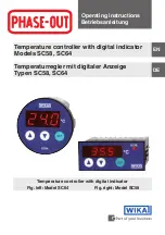
Fig. left: Model SC64

Fig. right: Model SC58

Содержание SC58

Страница 1: ...riebsanleitung EN DE Temperature controller with digital indicator Temperature controller with digital indicator Models SC58 SC64 Temperaturregler mit digitaler Anzeige Typen SC58 SC64 Fig left Model...

Страница 2: ...rn Prior to starting any work read the operating instructions Keep for later use Vor Beginn aller Arbeiten Betriebsanleitung lesen Zum sp teren Gebrauch aufbewahren 2 WIKA operating instructions model...

Страница 3: ...DE EN Contents 1 General information 4 2 Safety 5 3 Specifications 9 4 Design and function 10 5 Transport packaging and storage 12 6 Commissioning operation 13 7 Configuration 15 8 Maintenance and cl...

Страница 4: ...he operating instructions are part of the product and must be kept in the immediate vicinity of the instrument and readily accessible to skilled personnel at any time Skilled personnel must have caref...

Страница 5: ...nformation for efficient and trouble free operation DANGER identifies hazards caused by electric power Should the safety instructions not be observed there is a risk of serious or fatal injury 2 Safet...

Страница 6: ...emperature to equalise The manufacturer shall not be liable for claims of any type based on operation contrary to the intended use 2 2 Personnel qualification WARNING Risk of injury should qualificati...

Страница 7: ...ument the operating company must ensure that suitable first aid equipment is available and aid is provided whenever required that the operating personnel are regularly instructed in all topics regardi...

Страница 8: ...ructions CE Communaut Europ enne Instruments bearing this mark comply with the relevant European directives This marking on the instruments indicates that they must not be disposed of in domestic wast...

Страница 9: ...l SCxx 024 AC 230 V 50 60 Hz current consumption max 20 mA AC 12 24 V DC 12 36 V current consumption max 30 mA AC 230 V 50 60 Hz current consumption max 20 mA AC 12 24 V DC 16 36 V current consumption...

Страница 10: ...1 Description These temperature controllers feature simple operation and a high switch rating In comparison to mechanical thermostats these temperature controllers can handle significantly more switc...

Страница 11: ...E EN Model SC58 024 12 24 V 12 36 V 12 2 2 A 250 V K1 Model SC58 230 230 V 12 2 2 A 250 V K1 12 24 V 16 36 V K1 Pt100 16 2 2 A 250 V Model SC64 024 230 V K1 Pt100 16 2 2 A 250 V Model SC64 230 4 3 Con...

Страница 12: ...bjects Mechanical vibration mechanical shock putting it down hard Soot vapour dust and corrosive gases Potentially explosive environments flammable atmospheres Store the instrument in its original pac...

Страница 13: ...ors The controller and its connected installations contain live elements The housing must not be opened by the customer under any circumstances For any possible contact with live elements the instrume...

Страница 14: ...ents 5 It is advisable to provide a separate power cable for the control system s power supply so that noise levels introduced via the power cable are less strong and voltage drops when switching heav...

Страница 15: ...it the filter as close as possible to the controller and connect with short lines safe from touch The filter absolutely must be connected to a protective earth Note that a small reactive current flows...

Страница 16: ...key scrolls the list up the DOWN key scrolls it downwards If one presses the SET key the value of the respective parameter is displayed By then pressing the UP or DOWN keys the value is adjusted After...

Страница 17: ...sided setting the hysteresis is effective below for a heating contact above for a cooling contact With symmetrical hysteresis in both cases it is effective evenly above and below the switchpoint by a...

Страница 18: ...resis see parameter P32 is effectively a limit or band alarm The limit values with limit as well as band alarm can at any time be relative and thus concurrent with the set point S1 S1 or absolute so i...

Страница 19: ...3 0 the time monitoring is inactive 7 3 Third control level A parameter Setting of control parameters The third control level is accessible by first entering the second level and then scrolling up the...

Страница 20: ...d 2 A P parameter locked 0 A30 Type of alarm function 0 Limit alarm relative 1 Limit alarm absolute 2 Band alarm relative 3 Band alarm absolute 0 A31 Special function for alarm 0 not active 1 Display...

Страница 21: ...as two switch points A3 Function of the control contact on sensor error With a sensor error the controller contact adopts the state set here If an error is detected in the parameter memory display EP...

Страница 22: ...splayed in the normal state A40 Hysteresis mode control contact With this parameter it can be chosen whether the hysteresis at the respective switching point is symmetrical or single sided With hyster...

Страница 23: ...rameters and set values retain their numerical value and setting range Example A controller with a set point of 32 C is switched to Fahrenheit The new set point is interpreted as 32 F which correspond...

Страница 24: ...m actual value P30 see parameters P30 P31 P32 A30 A31 F3H Limit alarm actual value P31 see parameters P30 P31 P32 A30 A31 F3 Band alarm P30 actual value P31 see parameters P30 P31 P32 A30 A31 _ _ _ Ke...

Страница 25: ...turn 10 Dismounting return and disposal WARNING Residual media in the dismounted instrument can result in a risk to persons the environment and equipment Take sufficient precautionary measures 10 1 Di...

Страница 26: ...ghly sensitive measuring instrument Information on returns can be found under the heading Service on our local website 10 3 Disposal Incorrect disposal can put the environment at risk Dispose of instr...

Страница 27: ...DE Inhalt 1 Allgemeines 28 2 Sicherheit 29 3 Technische Daten 33 4 Aufbau und Funktion 34 5 Transport Verpackung und Lagerung 36 6 Inbetriebnahme Betrieb 37 7 Konfiguration 39 8 Wartung und Reinigung...

Страница 28: ...iften und allgemeinen Sicherheitsbestimmungen einhalten Die Betriebsanleitung ist Produktbestandteil und muss in unmittel barer N he des Ger tes f r das Fachpersonal jederzeit zug nglich aufbewahrt we...

Страница 29: ...mpfehlungen sowie Informatio nen f r einen effizienten und st rungsfreien Betrieb hervor GEFAHR kennzeichnet Gef hrdungen durch elektrischen Strom Bei Nichtbeachtung der Sicherheitshinweise besteht di...

Страница 30: ...peratur an die Raumtemperatur abwarten Anspr che jeglicher Art aufgrund von nicht bestimmungsgem er Verwendung sind ausgeschlossen 2 2 Personalqualifikation WARNUNG Verletzungsgefahr bei unzureichende...

Страница 31: ...Ger t muss der Betreiber sicherstellen dass eine entsprechende Erste Hilfe Ausr stung vorhan den ist und bei Bedarf jederzeit Hilfe zur Stelle ist dass das Bedienpersonal regelm ig in allen zutreffend...

Страница 32: ...ngt die Betriebsanleitung lesen CE Communaut Europ enne Ger te mit dieser Kennzeichnung stimmen berein mit den zutreffenden europ ischen Richtlinien Bei Ger ten mit dieser Kennzeichnung wird darauf hi...

Страница 33: ...V 50 60 Hz Stromaufnahme max 20 mA AC 12 24 V DC 12 36 V Stromaufnahme max 30 mA AC 230 V 50 60 Hz Stromaufnahme max 20 mA AC 12 24 V DC 16 36 V Stromaufnahme max 30 mA Schaltausgang Relais 12 A ohmsc...

Страница 34: ...Temperaturregler zeichnen sich durch eine einfache Bedienung und eine hohe Schaltleistung aus Im Vergleich zu einem mechanischen Thermostat k nnen diese Temperaturregler wesentlich mehr Schaltzyk len...

Страница 35: ...6 EN DE DE 4 3 Anschaltplan 4 3 1 Typ SC58 Typ SC58 024 12 24 V 12 36 V 12 2 2 A 250 V K1 Typ SC58 230 230 V 12 2 2 A 250 V K1 4 3 2 Typ SC64 12 24 V 16 36 V K1 16 2 2 A 250 V Typ SC64 024 230 V K1 16...

Страница 36: ...Mechanische Vibration mechanischer Schock hartes Aufstellen Ru Dampf Staub und korrosive Gase Explosionsgef hrdete Umgebung entz ndliche Atmosph ren Das Ger t in der Originalverpackung an einem Ort l...

Страница 37: ...d die mit ihm verbundenen Installationen enthalten spannungsf hrende Teile Das Geh use kundenseitig auf keinen Fall ffnen Bei m glichem Kontakt mit spannungsf hrenden Teilen das Ger t 2 polig vom Netz...

Страница 38: ...ie Spannungsver sorgung des Regelsystems vorzusehen wodurch St rpegel weniger stark ber die Netzleitung eingeschleppt werden und Spannungsein br che beim Schalten gro er Lasten weniger bemerkbar sind...

Страница 39: ...egler montieren und mit kurzen Leitungen ber hrungssicher verbinden Der Anschluss des Filters an Schutzerde ist unbedingt erforderlich Man beachte dass ein kleiner Blindstrom zur Erde abflie t Die Ver...

Страница 40: ...ch oben und mit der AB Taste wieder nach unten durchbl ttern Dr ckt man die SET Taste wird der Wert des jewei ligen Parameters angezeigt Durch zus tzliches Dr cken der AUF oder AB Taste wird der Wert...

Страница 41: ...g ist beim Heizkontakt die Hysterese nach unten wirksam beim K hlkontakt nach oben Bei symmetrischer Hysterese ist jeweils oberhalb und unterhalb des Schaltpunktes der halbe Wert der Hysterese wirksam...

Страница 42: ...rameter P32 wirksamer Grenzwert oder Bandalarm Die Grenzwerte k nnen sowohl beim Grenzwert als auch beim Bandalarm jeweils relativ also mit dem Sollwert S1 S1 mitlaufend sein oder absolut also unabh n...

Страница 43: ...ktiv 7 3 Dritte Bedienungsebene A Parameter Einstellung von Regelparametern Die dritte Bedienebene ist erreichbar indem zuerst die zweite Ebene aufgesucht wird und dort die Parameterliste bis zum h ch...

Страница 44: ...rriegelt 2 A P Parameter verriegelt 0 A30 Art der Alarmfunktion 0 Grenzwertalarm relativ 1 Grenzwertalarm absolut 2 Bandalarm relativ 3 Bandalarm absolut 0 A31 Sonderfunktion f r Alarm 0 nicht aktiv 1...

Страница 45: ...hlerfehler Bei F hlerfehler nimmt der Regelkontakt den hier eingestellten Zustand ein Falls ein Fehler im Parameterspeicher erkannt wird Anzeige EP und deshalb die eingespeicherten Einstellungen nicht...

Страница 46: ...zeigt wird A40 Hysteresemodus Regelkontakt Mit diesem Parameter kann gew hlt werden ob die Hysterese am jeweiligen Schaltpunkt symmetrisch oder einseitig wirksam ist Eine einseitig programmierte Hyste...

Страница 47: ...ameter und Sollwerte ihren Zahlenwert und Einstellbereich bei Beispiel Ein Regler mit Sollwert von 32 C wird auf Fahrenheit umgestellt Der neue Sollwert wird dann als 32 F interpretiert was einer Temp...

Страница 48: ...A30 A31 F3H Grenzwertalarm Istwert P31 siehe Parameter P30 P31 P32 A30 A31 F3 Bandalarm P30 Istwert P31 siehe Parameter P30 P31 P32 A30 A31 _ _ _ Tastenverriegelung aktiv siehe Parameter P19 bzw A19 B...

Страница 49: ...l 10 2 R cksendung beachten 10 Demontage R cksendung und Entsorgung WARNUNG Messstoffreste im ausgebauten Ger t k nnen zur Gef hrdung von Personen Umwelt und Einrichtung f hren Ausreichende Vorsichtsm...

Страница 50: ...nzeichnen Hinweise zur R cksendung befinden sich in der Rubrik Service auf unserer lokalen Internetseite 10 3 Entsorgung Durch falsche Entsorgung k nnen Gefahren f r die Umwelt entstehen Ger tekompone...

Страница 51: ...51 WIKA operating instructions models SC58 SC64 14054366 02 02 2016 EN DE...

Страница 52: ...g Germany Tel 49 9372 132 0 Fax 49 9372 132 406 info wika de www wika de 52 WIKA operating instructions models SC58 SC64 14054366 02 02 2016 EN DE WIKA subsidiaries worldwide can be found online at ww...

Отзывы: