background image

11

4 Mounting

WIKA Operating Instructions - Process pressure transmitter IPT-1*

2

1

1

Fig. 3: Position of the filter element

1  Filter element

2  Blind plug

Caution:

Due to the filter effect, the pressure compensation is time delayed. 

When opening/closing the housing cover quickly, the measured value 

can change for a period of approx. 5 s by up to 15 mbar.

Information:

Make sure that the filter element is always free of  buildup during 

operation. A high-pressure cleaner may not be used for cleaning.

Higher process temperatures mean often also higher ambient tem-

peratures.

1

2

Fig. 4: Temperature ranges

1  Process temperature

2  Ambient temperature

Make sure that the upper temperature limits for the environment of 

electronics housing and connection cable specified in chapter "

Tech-

nical data

" are not exceeded.

Instruments in the version "

Oil and grease free for oxygen

" should 

be unpacked just before mounting. After the protective cover of the 

process fitting has been removed, the label "O

2

" on the process fitting 

is visible.

Danger:

Avoid oil, grease or contamination. Explosion danger!

Temperature limits

Oxygen applications

Содержание IPT-1 series

Страница 1: ...Operating Instructions Process pressure transmitter IPT 1 Process pressure transmitter IPT 1 4 20 mA HART metallic sensor Version 3 0 ...

Страница 2: ...ing 4 1 General instructions 10 4 2 Mounting instructions 12 4 3 Installation procedure 12 5 Connecting to power supply 5 1 Preparing the connection 13 5 2 Connection procedure 14 5 3 Wiring plan single chamber housing 15 5 4 Wiring plan double chamber housing 17 5 5 Wiring plan double chamber housing Ex d 19 5 6 Wiring plan external housing with version IP 68 25 bar 21 5 7 Switch on phase 22 6 Se...

Страница 3: ...tary documentation Information Supplementary documents appropriate to the ordered version come with the delivery You can find them listed in chapter Product descrip tion Instructions manuals for accessories and replacement parts Tip To ensure reliable setup and operation of your IPT 1 we offer acces sories and replacement parts The corresponding documentations are Operating instructions manual Ext...

Страница 4: ...tip note This symbol indicates helpful additional information Caution If this warning is ignored faults or malfunctions can result Warning If this warning is ignored injury to persons and or serious damage to the instrument can result Danger If this warning is ignored serious injury to persons and or destruction of the instrument can result Ex applications This symbol indicates special instruction...

Страница 5: ...ut only by personnel authorised by the manufacturer Arbi trary conversions or modifications are explicitly forbidden 2 3 Warning about incorrect use Inappropriate or incorrect use of the instrument can give rise to application specific hazards e g vessel overfill or damage to system components through incorrect mounting or adjustment 2 4 General safety instructions This is a state of the art instr...

Страница 6: ...pressure on the type label see chapter 3 1 Configuration For safety reasons this range must not be exceeded 2 8 Fulfillment of NAMUR recommendations The device fulfills the requirements of the applicable NAMUR recom mendations 2 9 Safety instructions for Ex areas Please note the Ex specific safety information for installation and op eration in Ex areas These safety instructions are part of the ope...

Страница 7: ...ped with a supplementary label The supplementary label contains instructions on oil and grease free parts of the instru ment The IPT 1 consists of the components Process fitting with measuring cell Housing with electronics optionally available with plug connector Housing cover optionally available with display and adjustment module The components are available in different versions 1 2 3 Fig 1 Exa...

Страница 8: ...on on the same cable The supply voltage range can differ depending on the instrument ver sion The exact range is stated in chapter Technical data The backlight of the display and adjustment module is powered by the sensor The prerequisite for this is a supply voltage at a certain level The exact voltage specifications are stated in chapter Technical data 3 3 Operation The instrument can be adjuste...

Страница 9: ...nd possible transit damage immediately at receipt Ascertained transit damage or con cealed defects must be appropriately dealt with Up to the time of installation the packages must be left closed and stored according to the orientation and storage markings on the outside Unless otherwise indicated the packages must be stored only under the following conditions Not in the open Dry and dust free Not...

Страница 10: ...s later retrofitting of a display and adjustment module The housing can be rotated by 330 without the use of any tools You can also install the display and adjustment module in four different positions each displaced by 90 Use the recommended cables see chapter Connecting to power supply and tighten the cable gland You can give your instrument additional protection against moisture penetration by ...

Страница 11: ...cleaner may not be used for cleaning Higher process temperatures mean often also higher ambient tem peratures 1 2 Fig 4 Temperature ranges 1 Process temperature 2 Ambient temperature Make sure that the upper temperature limits for the environment of electronics housing and connection cable specified in chapter Tech nical data are not exceeded Instruments in the version Oil and grease free for oxyg...

Страница 12: ...e socket Use the seal corresponding to the instrument Process fitting GD Tesnit seal in front of the thread or Seal the thread with resistant seal material Process fitting GN Screw IPT 1 into the welded socket Tighten the hexagon on the process fitting with a suitable wrench Wrench size see chapter Dimensional drawings Warning The housing must not be used to screw the instrument in Applying tighte...

Страница 13: ...cted with standard two wire cable without screen If electromagnetic interference is expected which is above the test values of EN 61326 for industrial areas screened cable should be used Use cable with round cross section A cable outer diameter of 5 9 mm 0 2 0 35 in ensures the seal effect of the cable gland If you are using cable with a different diameter or cross section exchange the seal or use...

Страница 14: ... the potential connections within the instrument in chapter Technical data Take note of the corresponding installation regulations for Ex applica tions In particular make sure that no potential equalisation currents flow over the cable screen In case of grounding on both sides this can be achieved by the use of a capacitor or a separate potential equalisation 5 2 Connection procedure Proceed as fo...

Страница 15: ... the terminals by lightly pulling on them 10 Connect the screen to the internal ground terminal connect the outer ground terminal to potential equalisation 11 Tighten the compression nut of the cable entry gland The seal ring must completely encircle the cable 12 Screw the housing lid back on The electrical connection is finished 5 3 Wiring plan single chamber housing The following illustrations a...

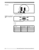
Страница 16: ... chamber housing 1 Plug connector for service 2 Spring loaded terminals for connection of the external display and adjust ment module 3 Ground terminal for connection of the cable screen 4 Spring loaded terminals for voltage supply I2C Display 1 1 2 5 6 7 8 Fig 7 Wiring plan single chamber housing 1 Voltage supply signal output Electronics and terminal compartment Wiring plan ...

Страница 17: ...er housing 1 Plug connector for service 2 Internal connection cable to the connection compartment 3 Terminals for the external display and adjustment unit 1 2 3 Display 1 2 I2C Fig 9 Terminal compartment double chamber housing 1 Spring loaded terminals for voltage supply 2 Plug connector for service interface 3 Ground terminal for connection of the cable screen Electronics compartment Terminal com...

Страница 18: ...ble chamber housing 1 Voltage supply signal output 3 4 1 2 Fig 11 Top view of the plug connector 1 Pin 1 2 Pin 2 3 Pin 3 4 Pin 4 Contact pin Colour connection ca ble in the sensor Terminal electronics module Pin 1 Brown 5 Pin 2 White 6 Pin 3 Blue 7 Pin 4 Black 8 Wiring plan Plug M12 x 1 for external display and adjustment unit ...

Страница 19: ...ent double chamber housing 1 Plug connector for service 2 Internal connection cable to the connection compartment 3 Terminals for the external display and adjustment unit 1 2 1 2 Fig 13 Connection compartment Ex d ia double chamber housing 1 Spring loaded terminals for power supply and cable screen 2 Ground terminal for connection of the cable screen Electronics compartment Terminal compartment ...

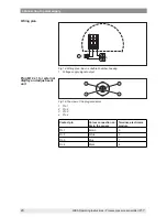
Страница 20: ...ouble chamber housing 1 Voltage supply signal output 3 4 1 2 Fig 15 Top view of the plug connector 1 Pin 1 2 Pin 2 3 Pin 3 4 Pin 4 Contact pin Colour connection ca ble in the sensor Terminal electronics module Pin 1 Brown 5 Pin 2 White 6 Pin 3 Blue 7 Pin 4 Black 8 Wiring plan Plug M12 x 1 for external display and adjustment unit ...

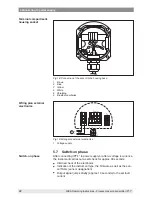
Страница 21: ...able outlet external housing 5 6 7 8 1 2 Display I C 2 1 5 4 3 Fig 17 Electronics and terminal compartment 1 Spring loaded terminals for voltage supply 2 Ground terminal for connection of the cable screen 3 Cable gland to the process component 4 For external display and adjustment unit Slave sensor 5 Plug connector for service interface Overview Electronics and connec tion compartment for power su...

Страница 22: ...lan external electronics 1 Voltage supply 5 7 Switch on phase After connecting IPT 1 to power supply or after a voltage recurrence the instrument carries out a self check for approx 30 seconds Internal check of the electronics Indication of the instrument type the firmware as well as the sen sor TAGs sensor designation Output signal jumps briefly approx 10 seconds to the set fault current Terminal...

Страница 23: ...ply WIKA Operating Instructions Process pressure transmitter IPT 1 Then the corresponding current is outputted to the cable the value corresponds to the actual level as well as the settings already carried out e g factory setting ...

Страница 24: ...ual Display and adjustment module 6 2 Insert display and adjustment module The display and adjustment module can be inserted and removed at any time It is not necessary to interrupt the voltage supply For installation proceed as follows 1 Unscrew the housing cover 2 Place the display and adjustment module in the desired position on the electronics you can choose any one of four different posi tion...

Страница 25: ... and adjustment module Note If you intend to retrofit the instrument with a display and adjustment module for continuous measured value indication a higher cover with an inspection glass is required 6 3 Adjustment system 2 3 1 1 1 Fig 21 Display and adjustment elements 1 LC display 2 Indication of the menu item number 3 Adjustment keys ...

Страница 26: ...RT Multidrop mode several sensors on one input the address must be set before continuing with the parameter adjustment You will find a detailed description in the operating instructions manual Display and adjustment module or in the online help of PACTware or DTM HART mode Standard Address 0 IPT 1 can be used for level as well as for process pressure meas urement Default setting is level measureme...

Страница 27: ...easured value is also displayed in the menu items for min max adjustment In this menu item you select the adjustment unit as well as the unit for the temperature indication in the display To select the adjustment unit in the example switching over from bar to mbar proceed as follows 2 1 Push the OK button in the measured value display the menu overview is displayed Basic adjustment Display Diagnos...

Страница 28: ...ith and confirm with OK and move to position correction with The adjustment unit is thus switched over from bar to m Proceed as follows to select the temperature unit 3 1 Activate the selection with OK and select Temperature unit with 2 Activate the selection with OK and select the requested unit with e g F 3 Confirm with OK The temperature unit is hence switched over from C to F Proceed as follow...

Страница 29: ...0 mbar 0000 0 mbar Information The displayed pressure for 100 corresponds to the nominal meas uring range of the sensor in the above example 1 bar 1000 mbar 2 Set the requested percentage value with and OK 3 Confirm with OK and edit the requested mbar value 4 Set the requested mbar value with and 5 Confirm with OK and move to the menu overview with ESC The max adjustment is finished Information Fo...

Страница 30: ...lready in the workshop without the instrument having to be installed The actual measured value is displayed in addition to the menu items for Zero Span adjustment IPT 1 is preset to application Level measurement Proceed as fol lows when switching over to application Process pressure measure ment 1 Push the OK button in the measured value display the menu overview is displayed 2 Select the menu Ser...

Страница 31: ...ver from bar to mbar Proceed as follows to select the temperature unit 5 1 Activate the selection with OK and select Temperature unit with 2 Activate the selection with OK and select the requested unit with e g F 3 Confirm with OK The temperature unit is hence switched over from C to F Proceed as follows 1 Activate in the menu item Position correction the selection with OK Position correction Offs...

Страница 32: ... mbar 0000 0 mbar Information The displayed pressure for 100 corresponds to the nominal meas uring range of the sensor in the above example 1 bar 1000 mbar 2 Set the requested mbar value with and OK 3 Confirm with OK and move to the menu overview with ESC The span adjustment is finished Information For an adjustment with pressure simply enter the actual measured value indicated at the bottom of th...

Страница 33: ...ll parameters adjusted by the user to the delivery status and the peak values to the actual values Reset Select reset Reset Basic adjustment Peak value measured value Peak value temperature Basic adjustment The Reset Basic adjustment resets the values of the following menu items Menu section Function Reset value Basic settings Zero Min adjustment Measuring range begin Span Max adjustment Measuring...

Страница 34: ...ure unit No reset Position correction No reset Display Backlight No reset Service SIL No reset Language No reset HART mode7 No reset Application No reset Peak value indicator The min and max temperature or pressure values are each reset to the actual value Additional adjustment and diagnosis options such as e g scaling simulation or trend curve presentation are shown in the following menu schemati...

Страница 35: ...0 mbar Max adjustment 1 4 100 00 100 00 mbar 0 0 mbar Damping 1 5 1 s Linearisation curve 1 6 Linear Sensor TAG 1 7 Sensor Display Basic adjustment 2 Display Diagnostics Service Info Displayed value 2 1 Pressure Displayed value 2 1 Scaled Display unit 2 2 Volume l Scaling 2 3 0 0 0 l 100 100 0 l Backlight 2 4 Switched off Diagnostics Basic adjustment 3 Display Diagnostics Service Info Peak value i...

Страница 36: ...ge using PC 5 3 Sensor characteristics 5 4 Display now 6 10 Saving the parameter adjustment data We recommended noting the adjusted data e g in this operating instructions manual and archiving them afterwards They are thus available for multiple use or service purposes If IPT 1 is equipped with a display and adjustment module the most important data can be read out of the sensor into the display a...

Страница 37: ...its with integrated HART resistance inner resist ance approx 250 Ω there is no additional external resistance neces sary Standard Ex separators are often provided with a sufficiently high current limitation resistance In such cases the modem can be connected in parallel to the 4 20 mA cable 7 2 Parameter adjustment with PACTware The further setup steps with detailed descriptions can be found in th...

Страница 38: ...lready implemented in the current versions of AMS and PDM For older versions of AMS and PDM a free of charge download is available via Internet Go via www wika com to the item Service 7 4 Saving the parameter adjustment data It is recommended to document or save the parameter adjustment data That way they are available for multiple use or service purposes The WIKA DTM Collection and PACTware in th...

Страница 39: ...oil leaks 8 2 Rectify faults The operator of the system is responsible for taking suitable meas ures to rectify faults IPT 1 offers maximum reliability Nevertheless faults can occur dur ing operation These may be caused by the following e g Sensor Process Voltage supply Signal processing The first measures to be taken are to check the output signals as well as to evaluate the error messages via th...

Страница 40: ...ed value available8 Exchange the instrument or send it in for repair E017 Adjustment span too small repeat with modified values E036 no operable sensor software Carry out a software update or send instrument for repair E041 Hardware error Exchange the instrument or send it in for repair Depending on the reason for the fault and the measures taken the steps described in chapter Set up may have to b...

Страница 41: ...xic products etc Take note of chapters Mounting and Connecting to power supply and carry out the listed steps in reverse order 9 2 Disposal The instrument consists of materials which can be recycled by spe cialised recycling companies We use recyclable materials and have designed the parts to be easily separable Materials see chapter Technical data If you have no way to dispose of the old instrume...

Страница 42: ...il Halocarbon oil9 10 Ʋ Ʋ Housing Plastic PBT Alu die casting powder coated 316L Ʋ Ʋ Seal between housing and housing cover NBR stainless steel housing silicone Aluminium housing Ʋ Ʋ Inspection window in housing cover for display and adjustment module Polycarbonate UL 746 C listed Ʋ Ʋ Ground terminal 316Ti 316L Ohmic contact Between ground terminal and process fitting Weight approx 1 2 kg 2 646 lb...

Страница 43: ...s adjustable Input variable Adjustment Adjustment range of the min max adjustment relating to the nominal measuring range Ʋ Ʋ Min 5 95 Ʋ Ʋ Max 5 105 Adjustment range of the zero span adjustment relating to the nominal measuring range Ʋ Ʋ Zero 5 95 Ʋ Ʋ Span 5 105 Recommended max turn down 10 1 no limitation Nominal measuring ranges and overload capability in bar kPa The specifications are only an o...

Страница 44: ... 2 0 2 bar 20 20 kPa 2 bar 200 kPa 1 bar 100 kPa Absolute pressure 0 0 4 bar 0 40 kPa 2 bar 200 kPa 0 bar abs 0 1 6 bar 0 160 kPa 10 bar 1000 kPa 0 bar abs 0 6 bar 0 600 kPa 35 bar 3500 kPa 0 bar abs 0 16 bar 0 1 6 MPa 80 bar 8 MPa 0 bar abs Nominal measuring ranges and overload capacity in psi The specifications are only an overview and refer to the measuring cell Limitations due to the ma terial...

Страница 45: ...fluence of the installation position depending on the chemical seal version Deviation determined according to the limit point method according to IEC 6077012 Applies to digital interfaces HART Profibus PA Foundation Fieldbus as well as to analogue current output 4 20 mA Specifications refer to the set span Turn down TD is the ratio nominal measuring range set span Deviation for measuring ranges 0 ...

Страница 46: ...cur rent output 4 20 mA Specifications refer to the set span Turn down TD nominal measuring range set span Long term drift of the zero signal 0 1 x TD year Ambient conditions Ambient storage and transport temperature Ʋ Ʋ Standard version 40 80 C 40 176 F Ʋ Ʋ Connection G1 A front flush according to EHEDG 10 80 C 14 176 F Ʋ Ʋ Version for oxygen applications13 40 60 C 40 140 F Ʋ Ʋ Versions IP 66 IP ...

Страница 47: ...the version 1 x blind stopper M20 x 1 5 Ʋ Ʋ Double chamber housing 1 x cable entry M20 x 1 5 cable ø 5 9 mm 1 x blind plug M20 x 1 5 plug M12 x 1 for the external display and adjustment unit optional or 1 x closing cap NPT 1 x blind plug NPT plug M12 x 1 for the external display and adjustment unit optional or 1 x plug depending on the version 1 x blind plug M20 x 1 5 plug M12 x 1 for the external...

Страница 48: ... DC Ʋ Ʋ Ex ia instrument 20 30 V DC Ʋ Ʋ Ex d instrument 20 36 V DC Permissible residual ripple Ʋ Ʋ 100 Hz Uss 1 V Ʋ Ʋ 100 Hz 10 kHz Uss 10 mV Load see diagram 1000 750 500 250 14 18 16 20 22 24 26 28 30 32 34 36 Ω V 4 1 2 3 Fig 25 Voltage diagram 1 HART load 2 Voltage limit Ex ia instrument 3 Voltage limit non Ex Ex d instrument 4 Operating voltage Electrical protective measures Protection rating ...

Страница 49: ...e 1oo1D up to SIL2 Ʋ Ʋ double channel diversitary redundant architecture 1oo2D up to SIL3 You will find detailed information in the Safety Manual of the instrument series Approvals Depending on the version instruments with approvals can have different technical data For these instruments please note the corresponding approval documents They are included in the scope of delivery 10 2 Dimensions Pla...

Страница 50: ...using is 9 mm 0 35 in higher 1 Single chamber version 2 Double chamber version Stainless steel housing 69 mm 2 72 ø 77 mm 3 03 117 mm 4 61 M20x1 5 NPT 59 mm 2 32 ø 80 mm 3 15 112 mm 4 41 M20x1 5 NPT 87 mm 3 43 M16x1 5 ø 84 mm 3 31 120 mm 4 72 M20x1 5 NPT 3 2 1 Fig 28 Housing versions with protection rating IP 66 IP 68 0 2 bar with integrated display and adjustment module the housing is 9 mm 0 35 i...

Страница 51: ...58 110 mm x 90 mm 4 33 x 3 54 66 mm 2 6 59 mm 2 32 Fig 29 IP 68 version with external housing plastic version 1 Lateral cable outlet 2 Axial cable outlet 1 2 65 mm 2 56 68 mm 2 68 92 mm 3 62 42 mm 1 65 40mm 1 58 110 mm x 90 mm 4 33 x 3 54 66 mm 2 6 59 mm 2 32 Fig 30 IP 68 version with external housing stainless steel version 1 Lateral cable outlet 2 Axial cable outlet ...

Страница 52: ...ing SW27 SW27 60 23mm 29 32 G A 63mm 2 31 64 57mm 2 1 4 15mm 19 32 3mm 1 8 ø 3mm 1 8 ø 6mm 15 64 NPT NPT 65mm 2 9 16 25mm 63 64 15mm 19 32 20mm 25 32 M 20x1 5 ND GD ML ø 4 8 3 16 MI SW27 60 57mm 2 1 4 12mm 15 32 M 16x1 5 ø 4 8 3 16 Fig 31 IPT 1 GD G EN 837 ND NPT ML M16 x 1 5 inner MI M20 x 1 5 inner ...

Страница 53: ...G1B G B 65 mm 2 9 16 ø 30 mm 1 3 16 SW60 22 mm 55 64 SW27 20 5 mm 13 16 ø 30 mm 1 3 16 ø 18 mm 45 64 G1 A 71 mm 2 51 64 SW41 28 mm 1 7 64 G1B68 mm 2 43 64 65 mm 2 9 16 85 G6 83 86 Fig 32 IPT 1 85 G1 A front flush 0 0 4 bar and 0 1 6 bar 86 G A front flush 1 6 bar 84 G1 A front flush up to 150 C according to EHEDG 0 0 4 bar and 0 16 bar ...

Страница 54: ...rt 2 51 mm 2 1 64 ø 84 mm 3 5 16 RT RA SA ø64 mm 2 33 64 82 mm 3 15 64 3T 3R ø 65 mm 2 9 16 ø 84 mm 3 5 16 ø 105 mm 4 9 64 82 mm 3 15 64 ø50 mm 1 31 32 82 mm 3 15 64 81 mm 3 3 16 ø 74 mm 2 29 32 Fig 33 IPT 1 SA Tri Clamp 2 RA slotted nut DN 40 PN 40 according to DIN 11851 RT Tri Clamp 1 3T DRD 3R Varivent Form F ...

Страница 55: ...55 Notes WIKA Operating Instructions Process pressure transmitter IPT 1 ...

Страница 56: ... 9372 132 0 Fax 49 9372 132 406 E mail info wika de www wika de 31543 EN 150511 All statements concerning scope of delivery application practi cal use and operating conditions of the sensors and processing systems correspond to the information available at the time of printing Process pressure transmitter IPT 1 ...

Отзывы: