


INSTRUCTION MANUAL
NI-210WE
Rev. 4 04/20
4 di 6
7.3 ELECTRICAL CONNECTIONS
It is recommended to carry out the electrical connections
according to the applicable standards. In case of intrinsic safety
instrument see also the Standard IEC-60079-14. If the electrical
connection is carried out in a protected tube, it shall be made so
that condensate is prevented from entering instrument enclosure
To guarantee the ingress protection IP66 and prevent loosening
of the blocking joint or cable glands, it is prescribed to seal the
threads with an anaerobic sealant. For example, use a sealant
like Loctite ® 542.
The installation of the cable gland or three-piece joint should be
as per Fig 5.
Fig. 5 – Installation of electrical connection
With the instrument into the final position provided that the
electric line is not energize, remove the cover and make the
electrical connection to the terminal block (see Fig. 2).
If the ambient temperature exceeds 60 °C is recommended to
use cables suitable for operating temperatures of at least 105 °C.
Flexible cables with a maximum section of 1,5 mm
2
(16AWG) are
recommended using the pre-insulated crimp ring terminal.
Ensure that no deposits or wire ends remain inside the case.
The relevant parameters for intrinsic safety are listed on the
nameplate of the instrument.
The tightening of the cable gland or the three-piece joint must be
performed as shown in Fig.6.
Fig.6 – Installation of the cable gland
As soon as connection steps are completed, mount the cover on
and make sure it is tight and blocked (see fig. 4).
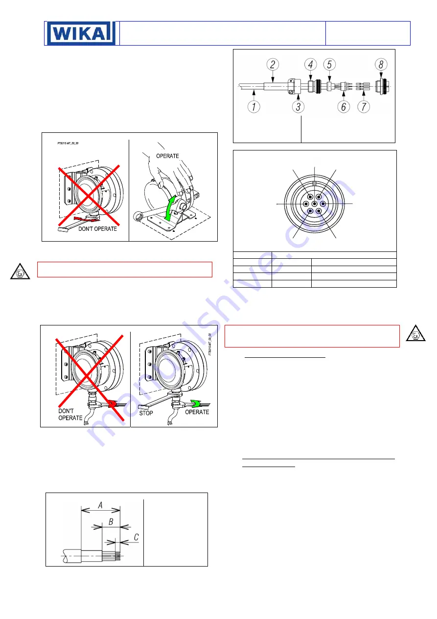
7.4 CONNETTOR 7 POLES TYPE MIL-5015 FOR
WEATHER PROOF INSTRUMENT
The free connector, supplied with the instrument, is able to
accept multicore cables with maximum outer diameter 11 mm. It
is recommended flexible cables with single-conductor with a
maximum section of 1.5 mm2 (16AWG).
The cable have to be prepared as per fig.7.
Fig. 7 – Cable preparation
A= 53mm
B= 30mm
C= 6,5 mm
The single stripped conductor has to be crimped with each
contact pin. For the electrical connections and for the assembly
follow Fig.8.
Fig.8 – Free connector assembly
1- Cable
2- Heat Shrink Boot
3- Clamp
4- Extender
5- Ferrule
6- Insulator for pin contacts
7- Pin contacts
8- Shell
The wiring diagram is according Fig.9.
Fig.9 – Wiring diagram MIL C-5015
CONTACT FUNCTION
A
1-NA
Micro 1: Normally open
B
1-NC
Micro 1: Normally closed
C
1-C
Micro 1: Common
G Ground
Internal
grounding
connection
Once the crimping and assembly activities of the free connector
are finished, make sure that all the parts are tight. Screw the
bayonet and tighten it to assure the instrument degree of
protection
7.5 GROUNDING
CONNECTIONS
The instrument is supplied with two grounding connections, one
external and one internal. The connections are suitable for a
earthing wires of 4 mm
2
section (fig. 2).
8 INSTRUMENT
PLUMBING
8.1 PLUMBING
CALIBRATION
DEVICE
This plumbing is necessary in order to prevent possible
tampering of set point. It is obtained with a stainless steel wire
inserted into the holes provided on the device (Fig.4). It is to be
done at the end of calibration.
8.2 PLUMBING ACCESS COVER TO TERMINAL
BLOCK
This plumbing is necessary in order to prevent possible
tampering of electric wiring. It is obtained with a stainless steel
wire (d) inserted into the holes of screws (c) and of blocking
racket (b) (Fig. 4). It is to be made after installing instrument on
the plant.
9 SAFETY INTEGRITY LEVEL (SIL) INSTALLATION
REQUIREMENTS
The pressure switch has been evaluated as Type A safety related
hardware. It has an hardware fault tolerance of 0 if it is used in
one out one configuration (1oo1). The installation has to be
designed to allow a proof test to detect dangerous undetected
fault using, as example, the following procedure:
-
Take appropriate action to avoid a false trip
-
Force the switch to reach a define max or min threshold
value and verify that output goes into the safe state.
-
Force the switch to reach a define normal threshold value
and verify that output goes into the normal state.
-
Repeat the check two times evaluating average set point
value and repeatability,
-
Restore the loop to full operation
-
Restore normal operation
A
B
C
D
F
G
E


