


14033590.01 10/2014 GB/D
WIKA operating instructions model CS4S
25
GB
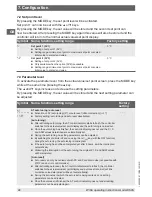
7.4 Auxiliary parameter level 1
To activate auxiliary parameter level 1, from the actual value/set point screen, press the
MODE key for approx. 3 seconds while at the same time pressing the ▼ key.
The ▲ and ▼ keys increase or decrease the setting parameters.
By pressing the MODE key, the set value will be stored and the next setting parameter can
be adjusted.
Symbol Name, function, setting range
Factory
setting
Loct
Locking level
■
Locks the adjustment of controller parameters, in order to prevent errors. Which
control parameters are locked depends on the locking level selected.
■
If locking level 1 or 2 is set, neither auto tuning nor auto reset can be carried out.
unlocked
----
(unlocked)
All controller parameters can be adjusted.
Loc1
(Locking Level 1) No controller parameters can be adjusted.
Loc2
(Locking Level 2) Only the set point can be adjusted.
Loc3
(Locking Level 3) All controller parameters can be adjusted, however the altered parameters
will not be stored permanently. If the controller is turned off, when it is
switched back on, the previous parameters will be reinstated. This mode is
used when values are only to be changed temporarily. This mode should be
set during operation of the controller via the serial interface.
hH
Maximum set point
■
Input of the upper limit for the set point.
■
Setting range:
minimum set point to maximum value of the input configuration or
minimum set point to scaled end value
Maximum value
of the input
configuration or
scaled end value
hL
Minimum set point
■
Input of the lower limit for the set point.
■
Setting range:
Minimum value of the input configuration to the maximum set
point or scaled start value to maximum set point
Minimum value
of the input
configuration
or scaled start
value
ho
Sensor correction
■
Input of the value for sensor correction
■
Setting range: -100.0 ... +100.0 °C (°F) or -1000 ... +1000
0.0 °C
cAhL
Communication protocol
■
Selection of the protocol for the communication via the serial interface
■
Only available when the option [CR5] is present
■
WIKA protocol:
noAL
Modbus ASCII mode:
AodA
Modbus RTU mode:
Aodr
WIKA protocol
cAno
Instrument address
■
Input of the instrument address for the controller
(if several instruments are operating on the same interface, each controller must
have a different instrument address set, otherwise no communication will be
possible)
■
Only available when the option [CR5] is present
■
Setting range: 0 to 95
0
7. Configuration
Содержание CS4S
Страница 46: ...14033590 01 10 2014 GB D 46 WIKA operating instructions model CS4S GB Appendix EC declaration of conformity...
Страница 90: ...14033590 01 10 2014 GB D 90 WIKA Betriebsanleitung Typ CS4S D Anlage EG Konformit tserkl rung...
Страница 91: ...WIKA operating instructions model CS4S 91 14033590 01 10 2014 GB D...