WifiTrax Model Science www.wifitrax.com WifiTrax Model Science www.wifitrax.com
(5)
CHECK YOUR WIRING!
Turn on the power. You may test the unit using
WFG-80 Web Pages described in the next section. Later you may decide to
use the Tower Operator App. Refer to the Tower Operator Quick Start, or
Full Help Pages for instructions on setting up a schematic control panel on
your Windows or Android computer or tablet.
Testing and Configuring your WFG-80
You can test and configure the WFG-80 using its web pages which are accessible
from any browser on IOS, Android or Windows.
Connecting using an Apple IOS Phone or Tablet
(1)
Tap the Settings icon on your iPhone or iPad
(2)
Tap Wi-Fi on the left-hand menu. Under Other Networks on the right, the
list should include one like wftrx_WFG80_1_XXXXXXXX_7, where XXXXXXXX
is the serial number of your unit that appears on its label. Tap that Wi-Fi
Network.
You must always connect to this Network to access the WFG-80
web pages
until you operate in home-net mode.
Connecting using Android
(1)
Press the Home button and tap the Settings icon:
(2)
Tap
Connections
, then Wi-
Fi and select the module’s network as
above.
Connecting using Windows
On your Windows 10 desktop or laptop, click the networks icon in the system
tray and select the network described above.
Testing using the WFG-80 Web pages
(1)
Once you are connected to the module’s network, open a browser such as
Safari, Chrome or Edge and type the following in the URL bar followed by
the Enter or Go key: 192.168.7.1
Links
added in
positions
shown for
bulbs
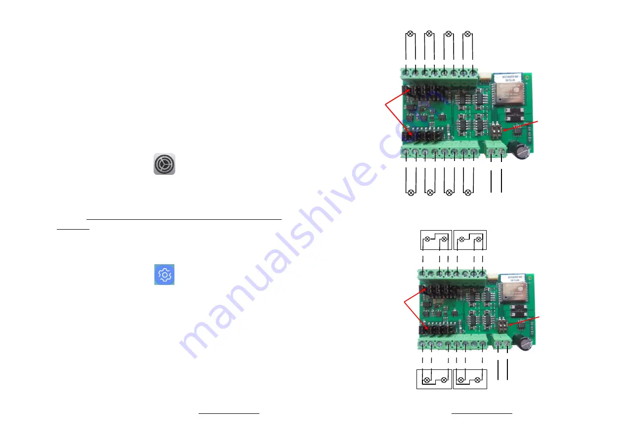
5- 5+ 6- 6+
7+
8+
7-
8-
Bank 2 Outputs
Switches Always in
ON position as
shown
Bulbs may be connected
either way around.
1+ 1- 2+ 2-
3-
4-
3+
4+
2+ 2- 3+ 3- 4+ 4-
Bank 1 Outputs
DC Power
+ -
Lamp1
Lamp2
Lamp3
Lamp4
Lamp5
Lamp6
Lamp7
Lamp8
Figure 3. Connection Diagram for Grain-of-Wheat Lamps
Links added in positions
shown for bulbs.
For LED Signals, remove
Links and connect
cathodes to negative
sides.
5- 5+ 6- 6+
7+
8+
7-
8-
Bank 2 Outputs
Switches Always in
ON position as
shown
Always connect common wires
to positive (+) termals
1+ 1- 2+ 2-
3-
4-
3+
4+
2+ 2- 3+ 3- 4+ 4-
Bank 1 Outputs
DC Power
+ -
Lamp1
Lamp2
Lamp3
Lamp4
Lamp 6
Lamp 5
Lamp 8
Lamp 7
RED
Common
Wire
Red
Wire
Green
Wire
RED
Common
Wire
Red
Wire
Green
Wire
GREEN
RED
Common
Wire
Red
Wire
Green
Wire
GREEN
RED
Common
Wire
Red
Wire
Green
Wire
Signal 3
Signal 4
Figure 4. Connection Diagram for 2-Light Signals


