


Phone: Toll Free 866.744.8722 Main 316.744.8722 • Fax: 316.744.1398 *
*
*
www.wiebetech.com
G5 JAM/JAM+
Installation MANUAL
Revised January 25, 2005
G5-JAM/JAM+
comes with Side Plate assembly, 4 or 8 screws for attaching hard disk drives, 1- 5/64 Allen
wrench, 1-SATA PCI card, 4 SATA cables, 1- Female to Female Special power connector, 2- Y-power
connector. Hard disk drives may be purchased with the G5 JAM/JAM+ or may be purchased separately. For
best performance, matching drives are recommended. Using drives with different brands and/or capacities
will result in a loss of performance and total RAID volume capacity.
Installation Instructions:
Begin by turning the G5 off and removing the side case cover along with the clear
plastic baffle.
Plan your installation:
Since there are different ways to configure your G5 JAM and JAM+, take a minute
to decide where the drives need to be mounted. If you are installing a G5 JAM with two drives, you may
install the drives down in front or up towards the top where they will fit inside the PCI card cavity. If you are
using the NVIDIA 6800 PCI card for the 30” display, then down in front is the best choice.
If there are no long or full-length PCI cards, then up in the PCI cavity is easiest. Once you have considered
the options and decided where the drives are to be mounted, continue with the installation.
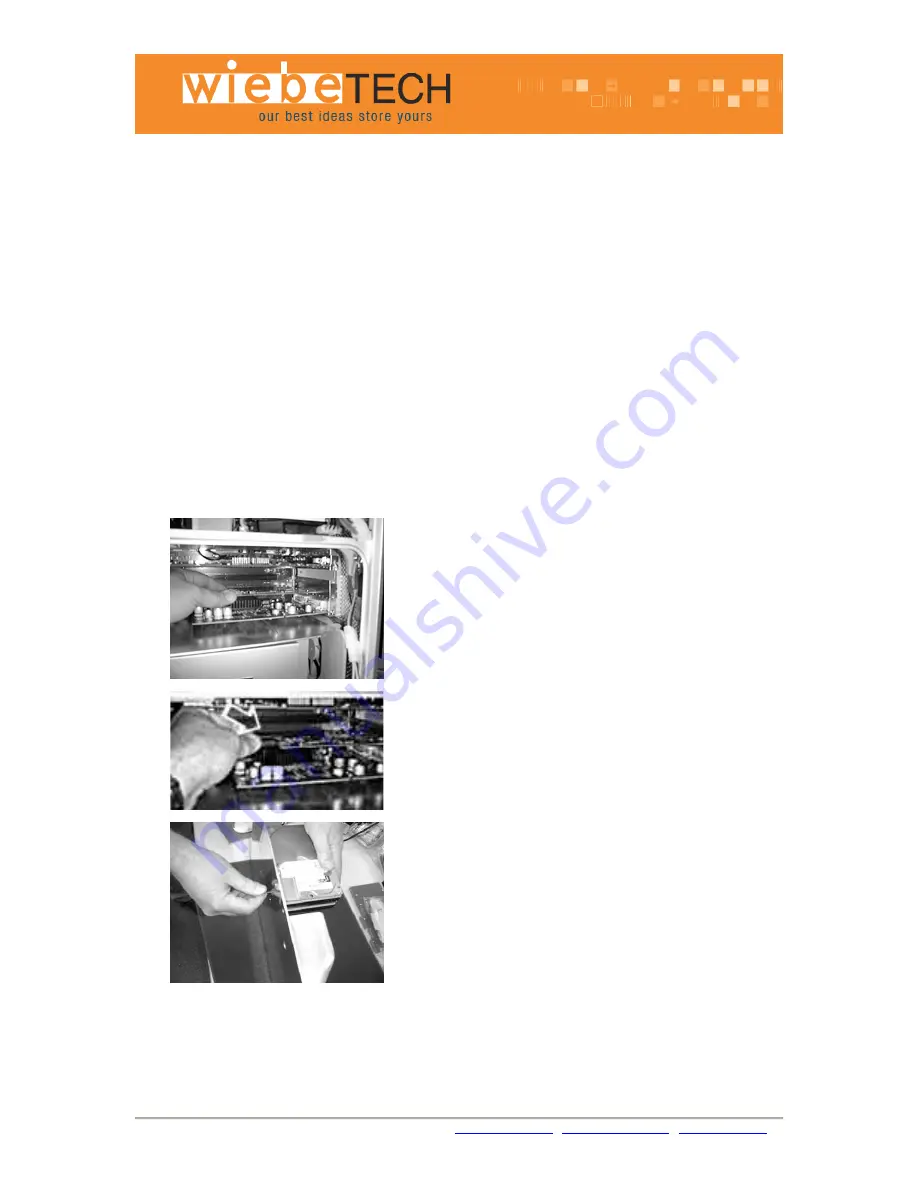
1.
Install PCI card.
Pay close attention to the Serial ATA PCI card. Note how the connectors are positioned
on the card. You will need to know how to connect the SATA cables to these connectors.
Install the SATA PCI card following any instructions provided with your G5 computer first.
If no instructions are available, use these instructions as a guide.
Remove the retaining screw and blank slot cover for the PCI slot you wish to use.
Install the Serial ATA PCI card in one of the available PCI slots of the G5. Be sure to
secure the card with the retaining screw that was removed from the blank slot cover. The
G5JAM+ has no preference as to which slot is used, but you may have other PCI cards
that do. The top slot will accommodate a longer PCI card with the G5JAM+ installed.
2.
Attach serial cables.
Attach the Serial ATA cables to the PCI card. There are two connectors for the G5 JAM
on the end of the card and four connectors for the G5 JAM+, facing the opening of the
G5.
3.
Attach the hard disk drives to the Side Plate
It is recommended to have a soft surface to work on. Choose a surface that will not
scratch the G5 JAM or JAM+, or be scratched by the metal edges. The foam from the
shipping box can be used for this purpose. There are no jumpers on the drives to set.
Attach the Hard disk drives to the polished aluminum Side Plate using the Allen head
screws included. Install the drives Label side up or facing the front, and with the drive
connectors facing what will be the back of the G5 when installed. Be sure to hold drives
securely when mounting them.
Mounting order does not matter. It is easiest to mount the two lower drives in front first.
Then the two top drives starting with the lower of the two drives.
Hard disk drive power cable installation.


