

193W/403W — PAGE 3
193W/403W Pedestal Base
ASSEMBLY INSTRUCTIONS
TOOLS REQUIRED:
Phillips Screwdriver, 5/32" Drill Bit, Drill, Adjustable Wrench or 9/16" & 1/2" Open End or
Box End Wrenches, Hammer, and Wood Glue.
We recommend using a Phillips bit on a variable speed drill.
This will make assembly easier and will eliminate the need for pre-drilling.
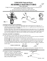
FIG. 2
A
G
J
GLUE ALL
DOWELS IN
THIS STEP.
BOX-END
OPEN-END
TO ATTACH THE FEET TO PEDESTAL:
2)
Glue a Dowel (J) into the upper hole in the end of each foot (A).
Screw the Hanger Bolts (G) into the pilot holes in the end of the Feet (A) as shown in FIGURE 2.
Rubbing a little soap on the threads will help them go in more easily.
For the 193W
leave approximately 1½" of the Hanger Bolt (G) exposed from the end of the foot.
For the 403W
leave approximately 2" of the Hanger Bolt (G) exposed from the end of the foot.
To avoid damaging the threads of the hanger bolt when screwing it in, use a pair of vise grips
on the area where the lag threads and machine threads meet or use the “double nut” method as
shown below.
DOUBLE NUT METHOD
With the “Double Nut” method, you lock two nuts together (turning them in opposite directions)
and then use a 9/16" or adjustable wrench on the outside nut to screw the bolts in.
TO ATTACH TOP SUPPORT TO PEDESTAL:
1)
Spread a thin film of glue on top of the Pedestal (B) before attaching the Top Support (C). To
screw the Top Support to the Pedestal, start all four 5/16 x 3" Lag Bolts (E) and Flat Washers (F)
into the Pedestal as shown in FIGURE 1.
Rubbing a little soap on the threads will help the screws go in more easily. Use a 1/2" or adjustable
wrench to tighten the screws firmly. Over-tightening could strip the wood. If you do strip the wood
in the Pedestal, spread some glue on a small wedge of wood or some wooden match sticks and
pound into the stripped hole. Allow this to dry several hours, then tighten the screws solidly.
BOX-END
OPEN-END
FIG. 1
E
E
E
E
C
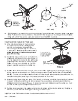
FIG. 3
L
A
K
3)
Screw the T-Nut (K) onto the Adjustable
Glides (L) as shown in FIGURE 3. Cover the
bottom of the Glide with a cloth to protect
from damage and lightly hammer them into
the Feet (A).
Do not
try to pull the Glides out
after you have them in place.
F
F


